

Potential Screening at Electrode/Ionic Liquid Interfaces from In Situ X-ray Photoelectron Spectroscopy
- PMID: 31844602
- PMCID: PMC6892450
- DOI: 10.1002/open.201900211
Potential Screening at Electrode/Ionic Liquid Interfaces from In Situ X-ray Photoelectron Spectroscopy
Abstract
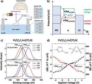
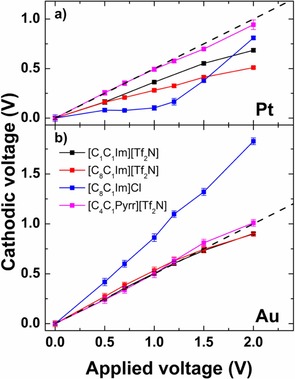
A new approach to investigate potential screening at the interface of ionic liquids (ILs) and charged electrodes in a two-electrode electrochemical cell by in situ X-ray photoelectron spectroscopy has been introduced. Using identical electrodes, we deduce the potential screening at the working and the counter electrodes as a function of applied voltage from the potential change of the bulk IL, as derived from corresponding core level binding energy shifts for different IL/electrode combinations. For imidazolium-based ILs and Pt electrodes, we find a significantly larger potential screening at the anode than at the cathode, which we attribute to strong attractive interactions between the imidazolium cation and Pt. In the absence of specific ion/electrode interactions, asymmetric potential screening only occurs for ILs with different cation and anion sizes as demonstrated for an imidazolium chloride IL and Au electrodes, which we assign to the different thicknesses of the electrical double layers. Our results imply that potential screening in ILs is mainly established by a single layer of counterions at the electrode.
Keywords: binding energies; electrodes; ionic liquids; photoelectron spectroscopy; potential screening.
© 2019 The Authors. Published by Wiley-VCH Verlag GmbH & Co. KGaA.
Conflict of interest statement
The authors declare no conflict of interest.
Figures
References
-
- None
-
- Armand M., Endres F., MacFarlane D. R., Ohno H., Scrosati B., Nat. Mater. 2009, 8, 621; - PubMed
-
- Osada I., de Vries H., Scrosati B., Passerini S., Angew. Chem. Int. Ed. 2016, 55, 500; - PubMed
-
- Kim T. Y., Lee H. W., Stoller M., Dreyer D. R., Bielawski C. W., Ruoff R. S., Suh K. S., ACS Nano 2011, 5, 436; - PubMed
-
- Abbott A. P., McKenzie K. J., Phys. Chem. Chem. Phys. 2006, 8, 4265. - PubMed
LinkOut - more resources
Full Text Sources
