Review
. 2019 Dec 13;20(24):6304.
doi: 10.3390/ijms20246304.

Strategies for Molecular Imprinting and the Evolution of MIP Nanoparticles as Plastic Antibodies-Synthesis and Applications

Affiliations
Review

Strategies for Molecular Imprinting and the Evolution of MIP Nanoparticles as Plastic Antibodies-Synthesis and Applications

Doaa Refaat et al. Int J Mol Sci. .

Abstract

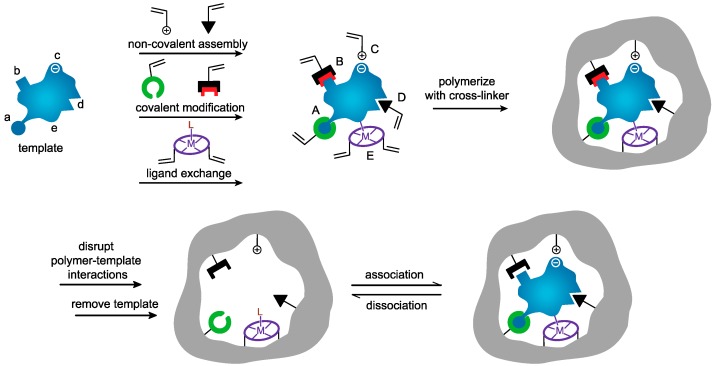
Materials that can mimic the molecular recognition-based functions found in biology are a significant goal for science and technology. Molecular imprinting is a technology that addresses this challenge by providing polymeric materials with antibody-like recognition characteristics. Recently, significant progress has been achieved in solving many of the practical problems traditionally associated with molecularly imprinted polymers (MIPs), such as difficulties with imprinting of proteins, poor compatibility with aqueous environments, template leakage, and the presence of heterogeneous populations of binding sites in the polymers that contribute to high levels of non-specific binding. This success is closely related to the technology-driven shift in MIP research from traditional bulk polymer formats into the nanomaterial domain. The aim of this article is to throw light on recent developments in this field and to present a critical discussion of the current state of molecular imprinting and its potential in real world applications.

Keywords: assay; molecular imprinting; nanoMIP; protein imprinting; sensor; therapeutic agent.


Conflict of interest statement

The authors declare no conflict of interest.

Figures

Figure 1
Figure 1
Schematic representation of the molecular imprinting process, reproduced from [16] with permission.
Figure 2
Figure 2
Schematic representations of protocols used in surface imprinting; (a) imprinting immobilized template on silica surfaces, reproduced from [35] with permission; (b) imprinting by surface grafting, reproduced from [36] with permission; and (c) soft lithography and UV initiated polymerization, adapted from [37] with permission.
Figure 2
Figure 2
Schematic representations of protocols used in surface imprinting; (a) imprinting immobilized template on silica surfaces, reproduced from [35] with permission; (b) imprinting by surface grafting, reproduced from [36] with permission; and (c) soft lithography and UV initiated polymerization, adapted from [37] with permission.
Figure 3
Figure 3
Epitope mapping: imprinting of the target protein (antigen), digestion of the protein to produce a peptide–polymer complex; isolation the peptide–polymer complex; and sequencing the attached peptide(s).
Figure 4
Figure 4
Schematic representation of micro-contact imprinting, reproduced from [61] with permission.
Figure 5
Figure 5
TNT and its less explosive analog TNP.
Figure 6
Figure 6
Several protocols used in preparation of nanoMIPs: (a) precipitation, (b) emulsion, (c) core–shell [2,92].
Figure 7
Figure 7
Schematic representation of solid phase synthesis of nanoMIPs.
Figure 8
Figure 8
Responses of blood type B or AB to the presence of blood type B-specific MIP nanoparticles. The black circles are magnetic disks on the inside walls of the microtiter plate wells.
Figure 9
Figure 9
A schematic representation of the MINA process: the microtiter plate well is coated with fluorescent nanoMIPs (yellow) linked to biotin (blue). The biotin is fixed on magnetic nanoparticles (brown). By addition of free target species to the tested well, a displacement of the nanoMIPs occurs with subsequent diffusion to the center enhancing the fluorescent signal. Reproduced from [152] with permission.
Figure 10
Figure 10
Fluorescence intensity of nanoMIPs displaced from the corresponding magNPs upon addition of incremental amounts of protein and incubation for 2 h. The excitation/emission filters used were 485 and 520 nm, adapted from data presented by Mahajan et al. [153].

References

    1. Chen B., Piletsky S., Turner A.P.F. Molecular Recognition: Design of “Keys”. Comb. Chem. High Throughput Screen. 2002;5:409–427. doi: 10.2174/1386207023330129. - DOI - PubMed
    1. Wackerlig J., Schirhagl R. Applications of molecularly imprinted polymer nanoparticles and their advances toward industrial use: A review. Anal. Chem. 2015;88:250–261. doi: 10.1021/acs.analchem.5b03804. - DOI - PubMed
    1. MIPdatabase. [(accessed on 10 December 2019)]; Available online: https://www.mipdatabase.com.
    1. Ansell R.J., Ramstrom O., Mosbach K. Towards artificial antibodies prepared by molecular imprinting. Clin. Chem. 1996;42:1506–1512. doi: 10.1016/S1074-5521(96)90095-2. - DOI - PubMed
    1. Hussain M., Wackerlig J., Lieberzeit P.A. Biomimetic Strategies for Sensing Biological Species. Biosensors. 2013;3:89–107. doi: 10.3390/bios3010089. - DOI - PMC - PubMed

Grants and funding

LinkOut - more resources