Review
. 2019 Dec 18;11(1):7.
doi: 10.3390/mi11010007.

Development Trends and Perspectives of Future Sensors and MEMS/NEMS

Affiliations
Review

Development Trends and Perspectives of Future Sensors and MEMS/NEMS

Jianxiong Zhu et al. Micromachines (Basel). .

Abstract

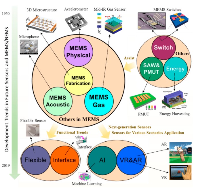
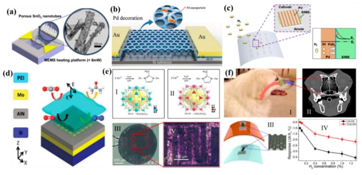
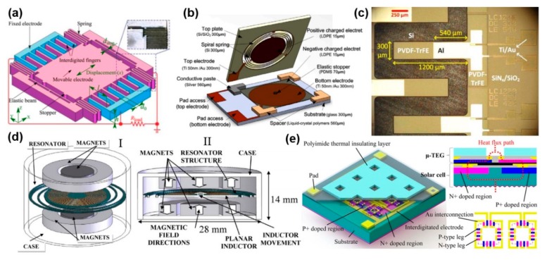
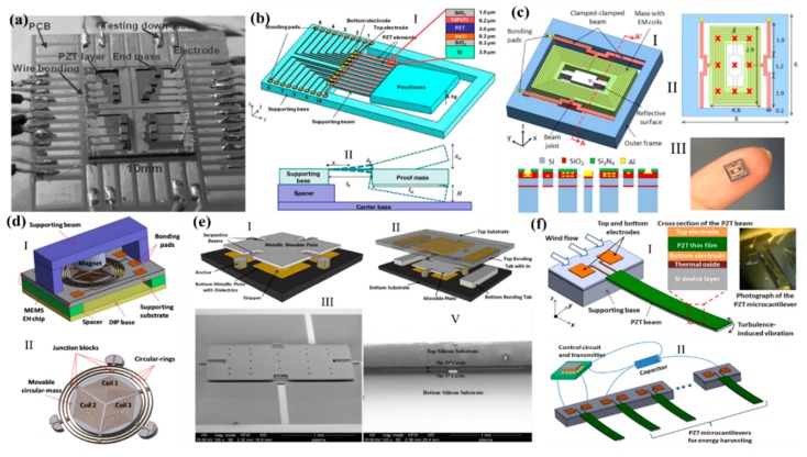
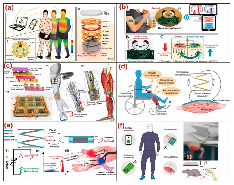
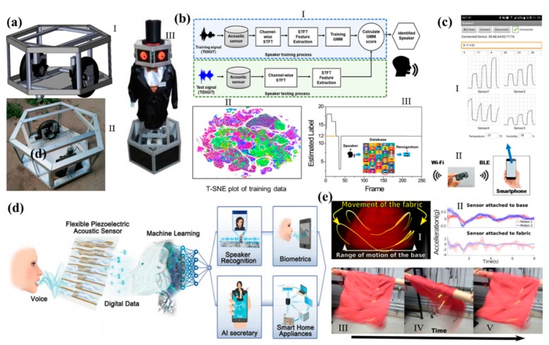
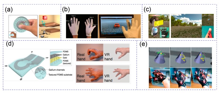
With the fast development of the fifth-generation cellular network technology (5G), the future sensors and microelectromechanical systems (MEMS)/nanoelectromechanical systems (NEMS) are presenting a more and more critical role to provide information in our daily life. This review paper introduces the development trends and perspectives of the future sensors and MEMS/NEMS. Starting from the issues of the MEMS fabrication, we introduced typical MEMS sensors for their applications in the Internet of Things (IoTs), such as MEMS physical sensor, MEMS acoustic sensor, and MEMS gas sensor. Toward the trends in intelligence and less power consumption, MEMS components including MEMS/NEMS switch, piezoelectric micromachined ultrasonic transducer (PMUT), and MEMS energy harvesting were investigated to assist the future sensors, such as event-based or almost zero-power. Furthermore, MEMS rigid substrate toward NEMS flexible-based for flexibility and interface was discussed as another important development trend for next-generation wearable or multi-functional sensors. Around the issues about the big data and human-machine realization for human beings' manipulation, artificial intelligence (AI) and virtual reality (VR) technologies were finally realized using sensor nodes and its wave identification as future trends for various scenarios.

Keywords: MEMS sensor; artificial intelligence; flexible sensor; human-machine interface; machine learning; zero-power sensor.


Conflict of interest statement

The authors declare no conflict of interest.

Figures

Figure 1
Figure 1
The development trends and perspectives of the future sensors and microelectromechanical systems (MEMS)/NEMS.
Figure 2
Figure 2
(a) Illustration of the typical fabrication of the MEMS sensor using bulk etching technology. (b) 3D view of a package with a wire bonding and a sealing technology. Adapted with permission from Torunbalci et al. [29]. (c) Schematics of a bandwidth tunable MEMS metamaterial supercell of microcantilever resonators with varying fixed and released lengths. Adapted with permission from Shih et al. [31]. (d) Schematic illustration of the two major methods involved in soft lithography. (e) A bendable microneedle array with a sharp tip and a lateral force was applied onto microneedle array. Adapted with permission from Wang et al. [35]. (f) Multi-layer MEMS structure was designed using direct laser writing technology, and the positioning and deposition processes were repeated. Adapted with permission from Reeves et al. [37].
Figure 3
Figure 3
Various mechanisms of the accelerometers and gyroscopes. (a) The schematic of a resonant accelerometer. Adapted with permission from Shin et al. [39]. (b) The schematic of a piezoelectric accelerometer with tri-axis, and its operation states under vertical acceleration and lateral acceleration. Adapted with permission from Zou et al. [43]. (c) The schematic of a piezoresistive accelerometer. Adapted with permission from Partridge et al. [46]. (d) The schematic of a 3-axis capacitive accelerometer and its sectional view. Adapted with permission from Tsai et al. [49]. (e) The schematic of a resonant disk gyroscope. Adapted with permission from Nitzan et al. [52]. (f) The schematic of a vibratory gyroscope. Adapted with permission from Giner et al. [55].
Figure 4
Figure 4
(a) Schematic of conventional capacitive MEMS microphone. (b) A no-back-plate capacitive microphone with interdigitated electrodes (IDTs) structure. Adapted with permission from Lo et al. [65]. (c) Bio-inspired piezoelectric microphone with a rectangular and a circular diaphragm. Adapted with permission from Rahaman et al. [69]. (d) Hybrid-mode microphone with a piezoelectric and a capacitive mechanism. Adapted with permission from Zhang et al. [71]. (e) Schematics of two optical microphones. Adapted with permission from Chen et al. [73].
Figure 5
Figure 5
(a) Scheme of a localization synthesis of ZnO nanowire and SnO2 on the MEMS microheater. Adapted with permission from Cho et al. [78]. (b) Schematic of the Pd-decorated Si nanomesh H2 sensor. Adapted with permission from Gao et al. [82]. (c) Graphical illustrations of a flexible Pd/Si nanomembrane gas sensor, and an energy band diagram demonstrating the H2 sensing mechanism with the Schottky barrier. Adapted with permission from Cho et al. [84]. (d) Complementary metal-oxide-semiconductor (CMOS) platform for CO2 sensing in mid-IR. Adapted with permission from Hasa et al. [85]. (e) Image of the deposition of zeolitic imidazolate framework (ZIF)-8 nanocrystals solution by a drop coating. Adapted with permission from Matatagui et al. [87]. (f) Biomimic laser-induced graphene (LIG) gas sensor. Adapted with permission from Zhu et al. [89].
Figure 6
Figure 6
(a) Schematics of the switching behavior of the Si fin. Van der Waals force will hold the fin in contact position even after the electrostatic force. Adapted with permission from Soon et al. [97]. (b) Structure of the piezoelectric actuators array and the two states of switching. Adapted with permission from Maharjan et al. [98]. (c) Schematic diagram of the proposed push-pull radio frequency (RF) MEMS switch. Adapted with permission from Cho et al. [100]. (d) Schematic representation of the piezoelectric mechanical transistor, showing the three-finger dual-beam design. Adapted with permission from Sinha et al. [104]. (e) Structure of the plasmonically-enhanced micromechanical photoswitches (PMP) and working principle with scanning electron microscope images with highlighted magnified views of the plasmonic absorber. Adapted with permission from Rajaram et al. [105].
Figure 7
Figure 7
(a) A typical structure of a surface acoustic wave (SAW). (b) SAW ID tag application in a car assembly line. Adapted with permission from Plessky et al. [112]. (c) A wireless temperature monitoring system. Adapted with permission from Ma et al. [113]. (d) Wireless underground temperature sensor system with SAW. Adapted with permission from Kim et al. [114]. (e) Acoustically driven wavelength-division multiplexers using SAW. Adapted with permission from Crespo-Poveda et al. [115]. (f) Lamb wave sensor to decouple the viscosity and density of the liquid. Adapted with permission from Wang et al. [117]. (g) High-performance piezoelectric micromachined ultrasonic transducer (PMUT) with a zero-bending membrane. Adapted with permission from Wang et al. [118]. (h) Broadband PMUT based on a mode-merging. Adapted with permission from Wang et al. [119].
Figure 8
Figure 8
(a) The schematic of an electrostatic energy harvester. Adapted with permission from Lu et al. [134]. (b) An electret energy harvester. Adapted with permission from Tao et al. [135]. (c) The SEM with a false-color of a piezoelectric energy harvester. Adapted with permission from Toprak et al. [136]. (d) The schematic of an electromagnetic energy harvester. Adapted with permission from Sardini et al. [137]. (e) Hybrid energy harvester with the piezoelectric and electromagnetic mechanism. Adapted with permission from Yan et al. [138].
Figure 9
Figure 9
(a) A prototype of an array for a broaden frequency harvesting. Adapted with permission from Liu et al. [139]. (b) Schematic illustration of a piezoelectric energy harvesting for frequency-up in a constraint space. Adapted with permission from Liu et al. [143]. (c) Electromagnetic energy harvesting with several spring modes for a wide range of frequency energy harvesting. Adapted with permission from Liu et al. [144]. (d) Schematically drawing of the proposed 3D vibration electromagnetic device driven by a low-frequency for energy harvesting. Adapted with permission from Liu et al. [145]. (e) MEMS capacitive energy harvesters using stoppers for a low and a wide range of frequency. Adapted with permission from Zhu et al. [146]. (f) A wide range frequency vibration source of a microcantilever immersed in a wind flow for wind sensing and its energy harvesting. Adapted with permission from Liu et al. [149].
Figure 10
Figure 10
(a) A battery-free wireless pressure and temperature dual sensors. Adapted with permission from Han et al. [153]. (b) A wearable biosensor for simultaneously monitoring sweat and interstitial fluid. Adapted with permission from Kim et al. [154]. (c) A triboelectric nanogenerator (TENG)-based neuromodulator for peripheral nerve stimulation. Adapted with permission from Lee et al. [155]. (d) A self-powered TENG system for direct muscle stimulation. Adapted with permission from Wang et al. [156]. (e) A diode-amplified TENG for high-efficiency muscle stimulation. Adapted with permission from Wang et al. [157]. (f) A current-enhanced TENG textile system for healthcare monitoring and rehabilitation applications. Adapted with permission from He et al. [158].
Figure 11
Figure 11
Triboelectric nanogenerator based human-machine interfaces. (a) Self-powered triboelectric based 3D-control sensor. Adapted with permission from Chen et al. [172]. (b) Multi-dimensional nano-manipulation terminal using strip sensors. Adapted with permission from Chen et al. [173]. (c) Conductive textile-based glove interface. Adapted with permission from He et al. [174]. (d) Flexible wearable patch for robotics manipulation. Adapted with permission from Chen et al. [175]. (e) Multi-functional and minimalist interface using a flexible wearable triboelectric patch. Adapted with permission from Shi et al. [177]. (f) Single-electrode bio-inspired spider-net-coding interface. Adapted with permission from Shi et al. [178].
Figure 12
Figure 12
(a) Illustration of the dynamic neural network (DNN) for the performance of the low-resonant-frequency piezoelectric MEMS energy harvester. Adapted with permission from Nevlydov et al. [180]. (b) Visual representations of the gaussian mixture model (GMM)-based machine learning algorithm for the speaker recognition, and the dataset of 90% used for training data, and 10% for testing data by 2800 training data of 40 people. Adapted with permission from Han et al. [184]. (c) Raw data transmission of multiple sensors through Wi-Fi for data transmission. Adapted with permission from Suh et al. [185]. (d) Schematic illustration of the promising applications using flexible piezoelectric acoustic sensors in response to the speaker’s voice and the data were trained using a machine learning-based model. Adapted with permission from Jung et al. [186]. (e) Effects of motion on fabric, the motion signals from sensors were located on both a rigid base and loosely attached to the base via the fabric. Adapted with permission from Michael et al. [187].
Figure 13
Figure 13
(a) A self-powered triboelectric based virtual reality (VR) 3D-control sensor. Adapted with permission from Chen et al. [172]. (b) A self-powered glove-based intuitive interface for diversified control applications in real/cyberspace. Adapted with permission from He et al. [174]. (c) A stretchable and transparent tactile sensor based on a hetero-contact microstructure for virtual human control. Adapted with permission from Liao et al. [190]. (d) Gallium-based thin films for wearable human motion sensors. Adapted with permission from Dejace et al. [191]. (e) A vibrotactile glove for identifying virtual 3D geometric shapes. Adapted with permission from Martinez et al. [192].

References

    1. Sun Y., Dong Y., Gao R., Chu Y., Zhang M., Qian X., Wang X. Wearable pulse wave monitoring system based on MEMS sensors. Micromachines. 2018;9:90. doi: 10.3390/mi9020090. - DOI - PMC - PubMed
    1. Lee C., Radhakrishnan R., Chen C.-C., Li J., Thillaigovindan J., Balasubramanian N. Design and modeling of a nanomechanical sensor using silicon photonic crystals. J. Light. Technol. 2008;26:839–846. doi: 10.1109/JLT.2007.915273. - DOI
    1. Lam K., Leo M., Lee C., Liang G. Design evaluation of graphene nanoribbon nanoelectromechanical devices. J. Appl. Phys. 2011;110:024302–024308. doi: 10.1063/1.3606578. - DOI
    1. Koh K., Kobayashi T., Lee C. Investigation of piezoelectric driven MEMS mirrors based on single and double s-shaped PZT actuator for 2-D scanning applications. Sens. Actuators A Phys. 2012;184:149–159. doi: 10.1016/j.sna.2012.06.018. - DOI
    1. Stange A., Imboden M., Javor J., Barrett L., Bishop D. Building a casimir metrology platform with a commercial MEMS sensor. Microsyst. Nanoeng. 2019;5:14. doi: 10.1038/s41378-019-0054-5. - DOI - PMC - PubMed

LinkOut - more resources