. 2019 Oct 24;6(24):1901437.
doi: 10.1002/advs.201901437. eCollection 2019 Dec.

Self-Sustainable Wearable Textile Nano-Energy Nano-System (NENS) for Next-Generation Healthcare Applications

Affiliations

Self-Sustainable Wearable Textile Nano-Energy Nano-System (NENS) for Next-Generation Healthcare Applications

Tianyiyi He et al. Adv Sci (Weinh). .

Abstract

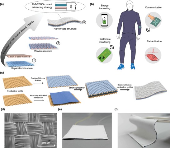
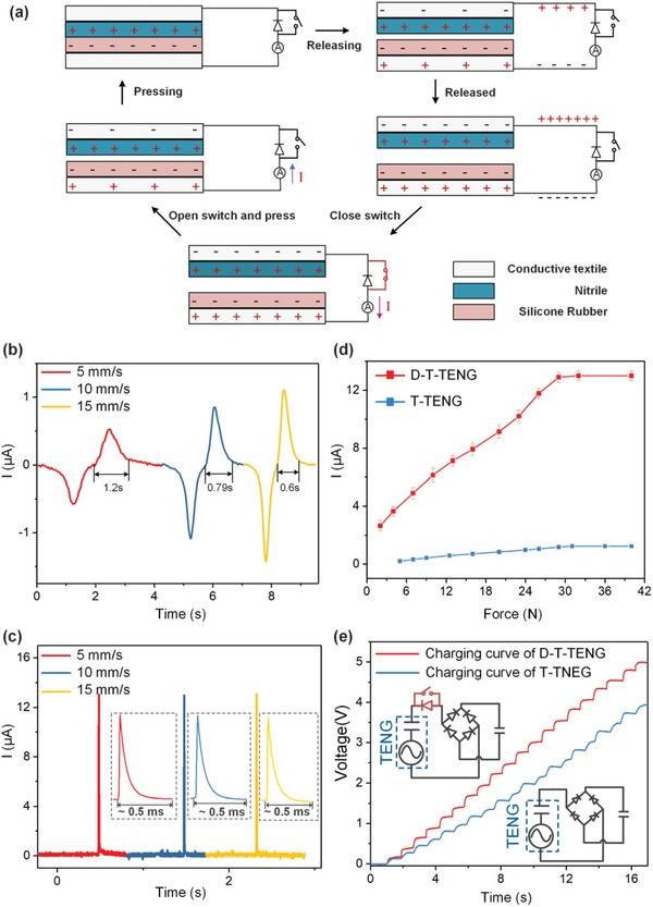
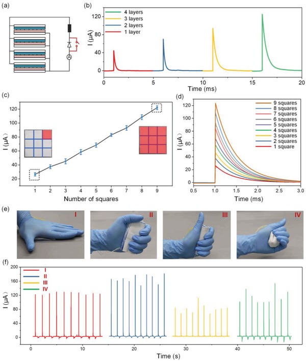
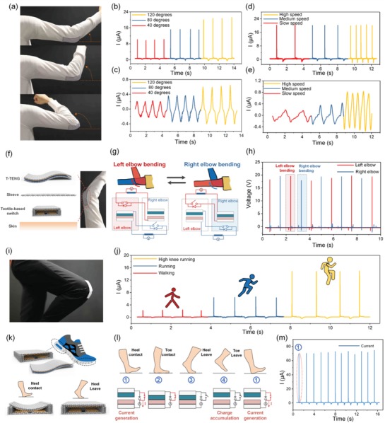
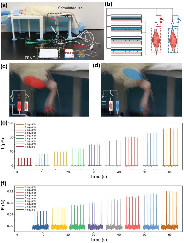
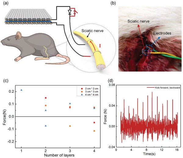
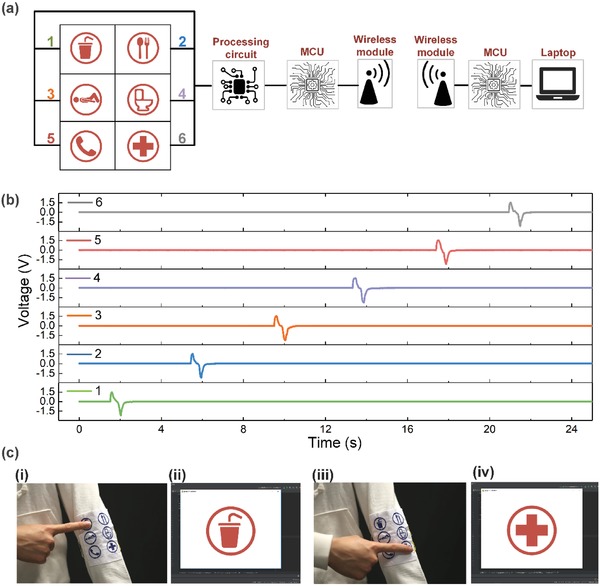
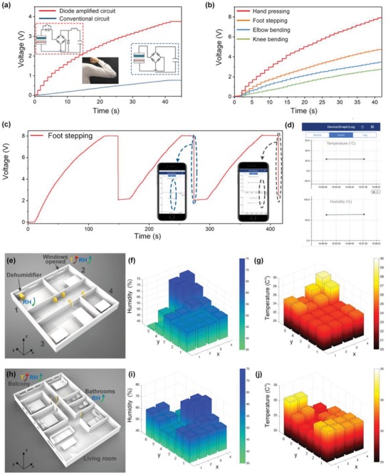
Wearable electronics presage a future in which healthcare monitoring and rehabilitation are enabled beyond the limitation of hospitals, and self-powered sensors and energy generators are key prerequisites for a self-sustainable wearable system. A triboelectric nanogenerator (TENG) based on textiles can be an optimal option for scavenging low-frequency and irregular waste energy from body motions as a power source for self-sustainable systems. However, the low output of most textile-based TENGs (T-TENGs) has hindered its way toward practical applications. In this work, a facile and universal strategy to enhance the triboelectric output is proposed by integration of a narrow-gap TENG textile with a high-voltage diode and a textile-based switch. The closed-loop current of the diode-enhanced textile-based TENG (D-T-TENG) can be increased by 25 times. The soft, flexible, and thin characteristics of the D-T-TENG enable a moderate output even as it is randomly scrunched. Furthermore, the enhanced current can directly stimulate rat muscle and nerve. In addition, the capability of the D-T-TENG as a practical power source for wearable sensors is demonstrated by powering Bluetooth sensors embedded to clothes for humidity and temperature sensing. Looking forward, the D-T-TENG renders an effective approach toward a self-sustainable wearable textile nano-energy nano-system for next-generation healthcare applications.

Keywords: healthcare; nanoenergy nano‐system (NENS); self‐sustainable; textiles; triboelectric.


Conflict of interest statement

The authors declare no conflict of interest.

Figures

Figure 1
Figure 1
a) Road map showing the evolution of the T‐TENGs. b) Illustration of the wearable textile NENS for the next‐generation healthcare applications. c) Fabrication process of the T‐TENG. d) SEM image of the conductive textile. e,f) Images of the narrow‐gap and soft TENG textile on a table and curved by a tweezer.
Figure 2
Figure 2
Basic characterization of the D‐T‐TENG. a) Working mechanism of the D‐T‐TENG. Current waveform of the b) T‐TENG and c) D‐T‐TENG under pressing/ releasing speed of 5, 10, and 15 mm s−1. d) Peak current of the D‐T‐TENG and T‐TENG as a function of applied forces at a constant pressing/releasing speed of 15 mm s−1. e) Charging curve of the D‐T‐TENG and T‐TENG on a 1 µF capacitor. The upper inset shows the circuit diagram of the D‐T‐TENG, and the bottom one is the circuit diagram for T‐TENG.
Figure 3
Figure 3
Current modulation of the D‐T‐TENG. a) Circuit diagram of the four‐layered D‐T‐TENG. b) Closed‐loop current on a 1 MΩ load of the D‐T‐TENG with different number of layers. c) Controllable peak current of the four‐layered D‐T‐TENG when pressed on different sizes of areas. d) Enlarged current profile of the D‐T‐TENG as the pressed area increases from one square to nine squares. e) Images of the four‐layered TENG textile being pressed normally (I), folded and pressed (II), rolled and pressed (III), random scrunched (IV). f) Corresponding current output under the four operation conditions.
Figure 4
Figure 4
Energy harvesting from various body motions. a) Images of the elbow bending at around 40°, 80°, and 120°. Current of the b) D‐T‐TENG and c) T‐TENG as the elbow bending at different angles. d,e) Current of the d) D‐T‐TENG and e) T‐TENG when the elbow bends at 120° with ascending speeds. f) Exploded view of the functional sleeve embedded with T‐TENG on the outside and a textile‐based switch on the inside. g) Circuit diagram and working mechanism of the left‐elbow (red) and the right‐elbow (blue) D‐T‐TENG. h) Voltages waveform as the two elbows bend alternatively. i) Images of a TENG textile attached to the trousers on the knee location. j) Current of the D‐T‐TENG on knee as the user is walking, running, and doing high‐knee running. k) Images showing the locations of the TENG textile and the textile‐based switch (up), and the structure variation as the switch is pressed by heel (bottom). l) Working mechanism of the D‐T‐TENG on foot while walking. m) Current of the D‐T‐TENG while walking.
Figure 5
Figure 5
Direct muscle stimulation with the D‐T‐TENG. a) Images of the testing set up for the rat tibialis anterior muscle and gastrocnemius muscle stimulation. b) Circuit diagram of selective muscle stimulation. c) Image of the rat leg motion when the tibialis anterior muscle is stimulated. d) Image of the rat leg motion when the tibialis gastrocnemius muscle is stimulated. e) Current profile over a 1 MΩ load of the D‐T‐TENG when different number of squares are pressed. f) The corresponding force profile of the rat leg when it is induced to move forward by pressing different number of squares of the D‐T‐TENG.
Figure 6
Figure 6
Direct nerve stimulation with the D‐T‐TENG. a) Image showing the testing set up for rat sciatic nerve stimulation. b) Enlarged photo of the sciatic nerve connected to the stimulation electrodes. c) Force distribution of the leg motions when it is stimulated by D‐T‐TENG with different sizes and layers. d) Recorded force profile when the sciatic nerve is stimulated by a four‐layered D‐T‐TENG with a size of 2 cm × 2 cm.
Figure 7
Figure 7
Wearable wireless communication board. a) Circuit connection of the wireless communication board system. b) Voltages signals collected from the MCU as the six pixels are pressed one by one. c) Photos of the textile‐based communication board integrated on an actual garment when it is pressed on the first (i) and last (iii) pixel, and the corresponding icons displayed on the screen (ii and iv).
Figure 8
Figure 8
D‐T‐TENG powered Bluetooth sensing. a) Charging curves on the 27 µF capacitor of the D‐T‐TENG and T‐TENG as the elbow bends 120°. The insets show the circuit diagram for the D‐T‐TENG (left) and for the sole T‐TENG (right). b) Charging curves with the D‐T‐TENGs from different body parts. c) Charging and discharging curve with the D‐T‐TENG on foot, where each voltage drop represents a discharging to the Bluetooth module. d) Enlarged screenshot on a smartphone showing the collected information from the Bluetooth module. e) 3D layout of a lab environment. f,g) Humidity and temperature distribution of the lab environment with 20 sampling points. h) 3D layout of an apartment. i,j) Humidity and temperature distribution of the apartment with 24 sampling points.

References

    1. Tian X., Lee P. M., Tan Y. J., Wu T. L. Y., Yao H., Zhang M., Li Z., Ng K. A., Tee B. C. K., Ho J. S., Nat. Electron. 2019, 2, 243.
    1. Chu B., Burnett W., Chung J. W., Bao Z., Nature 2017, 549, 328. - PubMed
    1. Wang X., Dong L., Zhang H., Yu R., Pan C., Wang Z. L., Adv. Sci. 2015, 2, 1500169. - PMC - PubMed
    1. Zhou Z., Li X., Wu Y., Zhang H., Lin Z., Meng K., Lin Z., He Q., Sun C., Yang J., Wang Z. L., Nano Energy 2018, 53, 501.
    1. Shi Q., Qiu C., He T., Wu F., Zhu M., Dziuban J. A., Walczak R., Yuce M. R., Lee C., Nano Energy 2019, 60, 545.

LinkOut - more resources