

Investigation on the Fiber Orientation Distributions and Their Influence on the Mechanical Property of the Co-Injection Molding Products
- PMID: 31877622
- PMCID: PMC7023512
- DOI: 10.3390/polym12010024
Investigation on the Fiber Orientation Distributions and Their Influence on the Mechanical Property of the Co-Injection Molding Products
Abstract
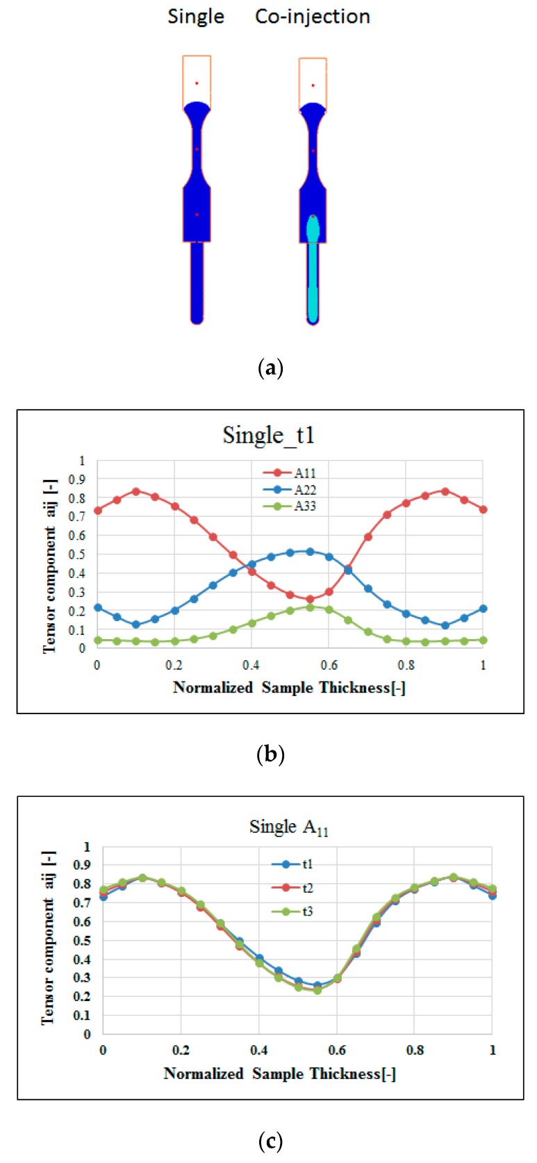
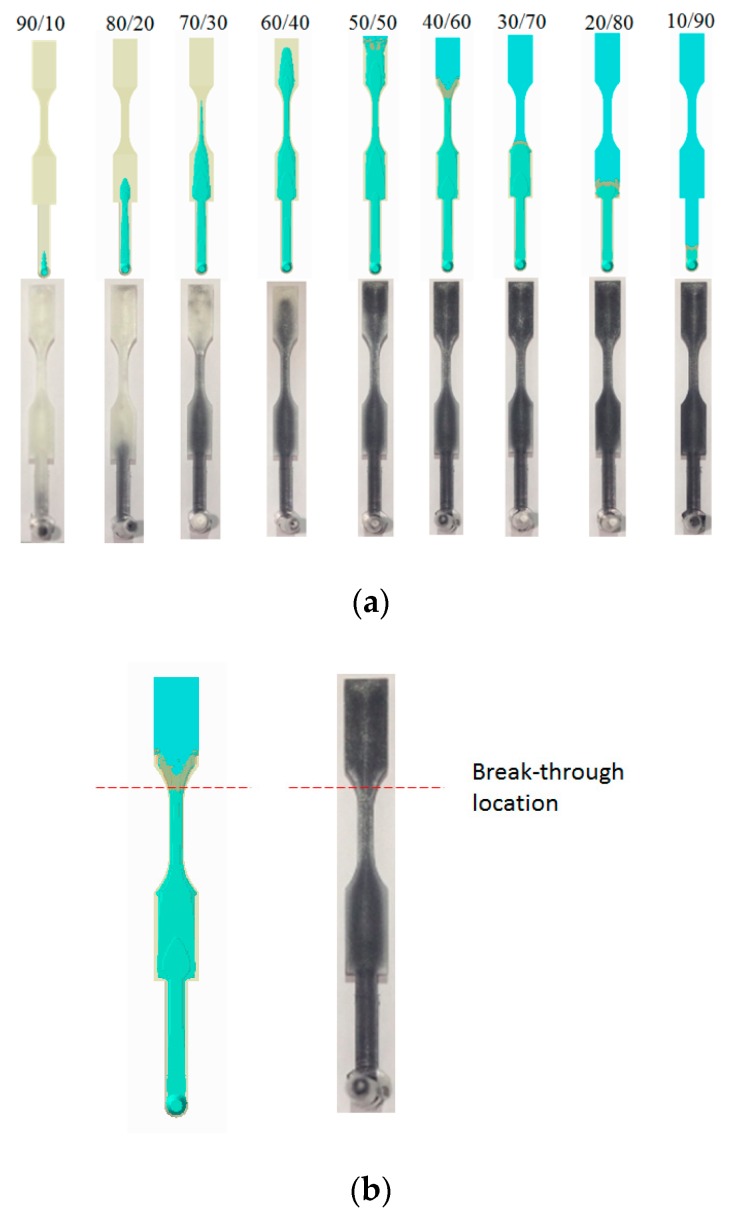
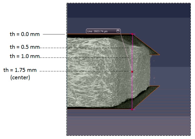
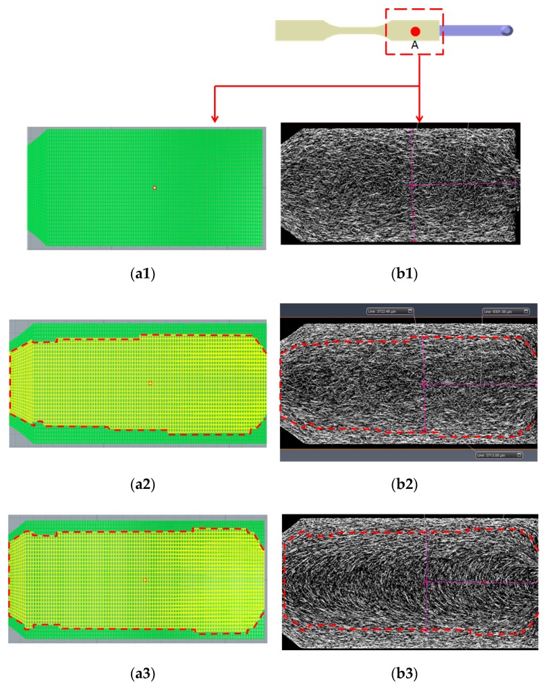
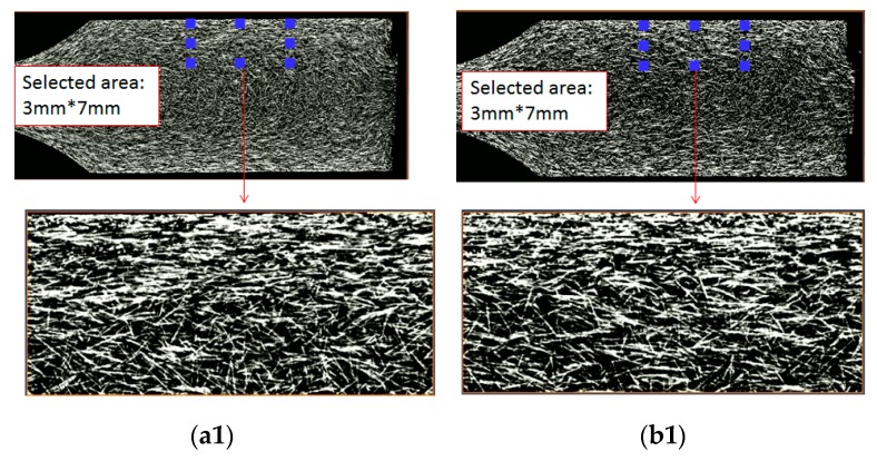
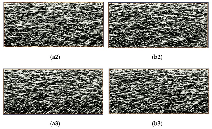
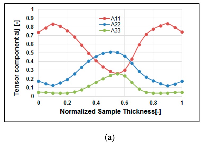
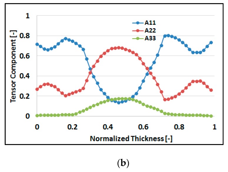
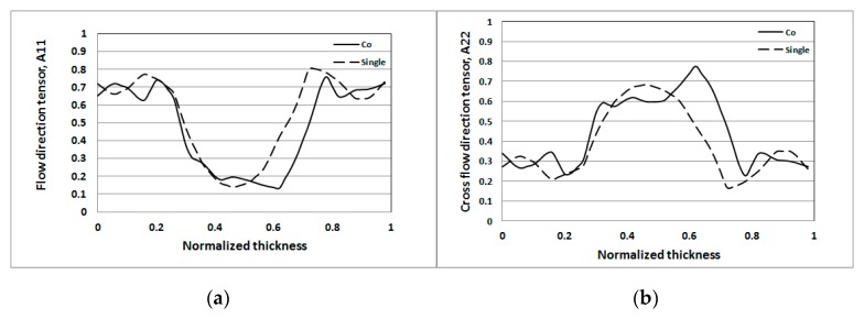
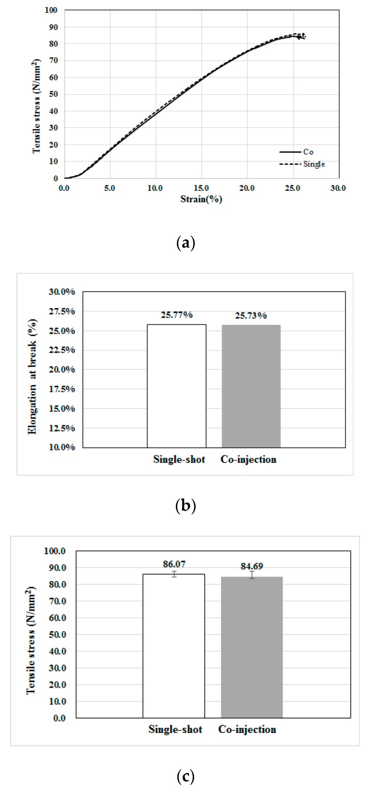
In recent years, due to the rapid development of industrial lightweight technology, composite materials based on fiber reinforced plastics (FRP) have been widely used in the industry. However, the environmental impact of the FRPs is higher each year. To overcome this impact, co-injection molding could be one of the good solutions. But how to make the suitable control on the skin/core ratio and how to manage the glass fiber orientation features are still significant challenges. In this study, we have applied both computer-aided engineering (CAE) simulation and experimental methods to investigate the fiber feature in a co-injection system. Specifically, the fiber orientation distributions and their influence on the tensile properties for the single-shot and co-injection molding have been discovered. Results show that based on the 60:40 of skin/core ratio and same materials, the tensile properties of the co-injection system, including tensile stress and modulus, are a little weaker than that of the single-shot system. This is due to the overall fiber orientation tensor at flow direction (A11) of the co-injection system being lower than that of the single-shot system. Moreover, to discover and verify the influence of the fiber orientation features, the fiber orientation distributions (FOD) of both the co-injection and single-shot systems have been observed using micro-computerized tomography (μ-CT) technology to scan the internal structures. The scanned images were further utilizing Avizo software to perform image analyses to rebuild the fiber structure. Specifically, the fiber orientation tensor at flow direction (A11) of the co-injection system is about 89% of that of the single-shot system in the testing conditions. This is because the co-injection part has lower tensile properties. Furthermore, the difference of the fiber orientation tensor at flow direction (A11) between the co-injection and the single-shot systems is further verified based on the fiber morphology of the μ-CT scanned image. The observed result is consistent with that of the FOD estimation using μ-CT scan plus image analysis.
Keywords: co-injection molding; fiber orientation distribution (FOD); fiber reinforced plastics (FRP); micro-computerized tomography (μ-CT) scan technology.
Conflict of interest statement
The authors declare no conflict of interest.
Figures


References
-
- Hammond L.-A. BMW i3 Carbon Fiber Aluminum Body Frame a New Ara in Electromobility. [(accessed on 10 December 2019)]; Available online: https://www.drivingthenation.com/bmw-i3-carbon-fiber-aluminum-body-frame...
-
- Jacob A. Carbon fibre and cars-2013 in review. In Reinforced Plastics. [(accessed on 10 December 2019)];2014 Available online: https://www.materialstoday.com/carbon-fiber/features/carbon-fibre-and-ca...
-
- Amaechi C.-V., Agbomerie C.-O., Orok E.-O., Job S., Ye J. Reference Module in Materials Science and Materials Engineering. Elsevier; Amsterdam, The Netherlands: 2019. Economic aspects of fiber reinforced polymer composite recycling. - DOI
-
- Wood L. Global Composites Market Report 2019: $40.2 Billion Market Trends, Forecast and Competitive Analysis 2013–2018 & 2019–2024, Dublin. [(accessed on 10 December 2019)]; Available online: https://www.globenewswire.com/news-release/2019/04/12/1803326/0/en/Globa....
-
- Witten E., Mathes V., Sauer M., Kuhnel M. Composites Market Report 2018: Market Developments, Trends, Outlooks and Challenges. AVK & Carbon Composites. [(accessed on 8 December 2019)]; Available online: https://eucia.eu/userfiles/files/20181115_avk_ccev_market_report_2018_fi....
Grants and funding
LinkOut - more resources
Full Text Sources
Research Materials
Miscellaneous
