. 2019 Dec 27;14(12):e0226421.
doi: 10.1371/journal.pone.0226421. eCollection 2019.

Improving accuracy for finite element modeling of endovascular coiling of intracranial aneurysm

Affiliations

Improving accuracy for finite element modeling of endovascular coiling of intracranial aneurysm

Robert J Damiano et al. PLoS One. .

Abstract

Background: Computer modeling of endovascular coiling intervention for intracranial aneurysm could enable a priori patient-specific treatment evaluation. To that end, we previously developed a finite element method (FEM) coiling technique, which incorporated simplified assumptions. To improve accuracy in capturing real-life coiling, we aimed to enhance the modeling strategies and experimentally test whether improvements lead to more accurate coiling simulations.

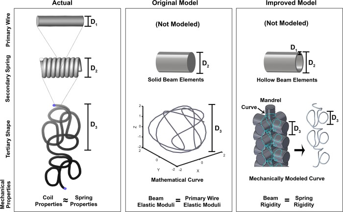
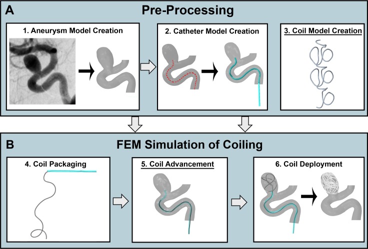
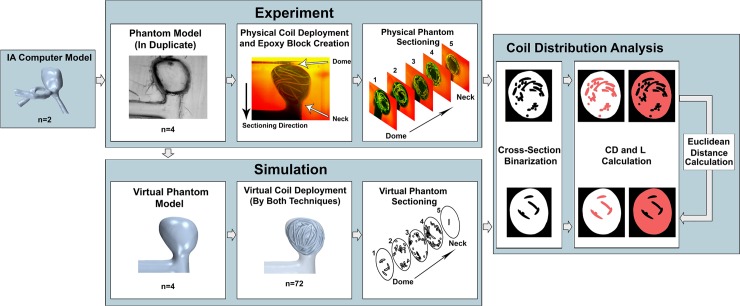
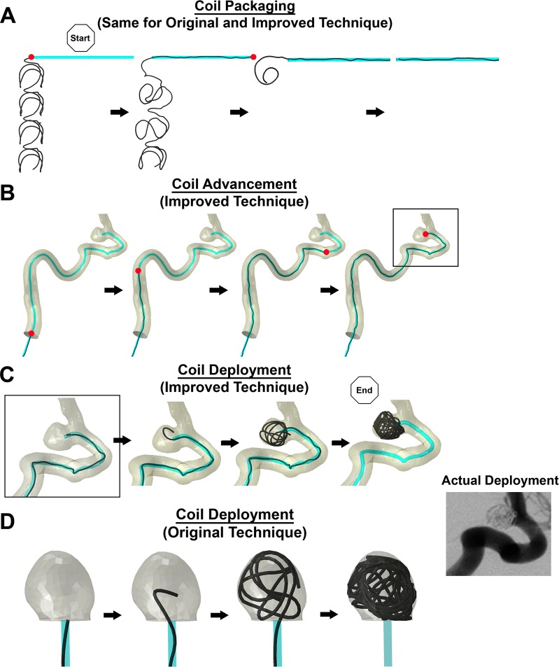
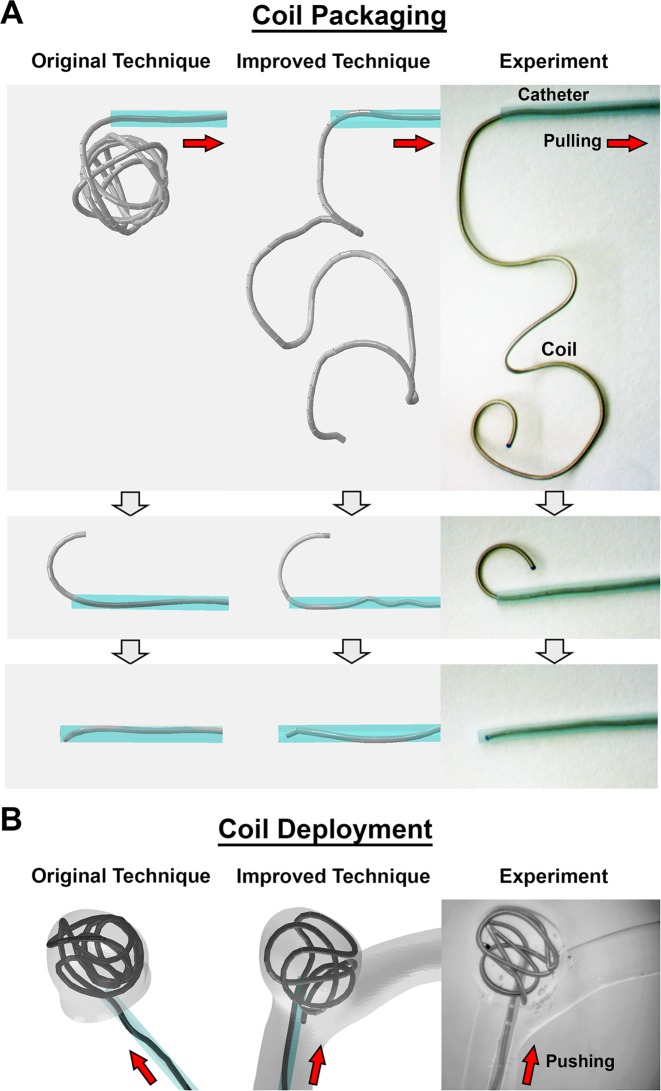
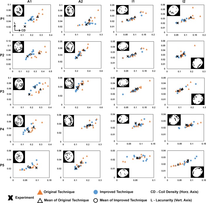
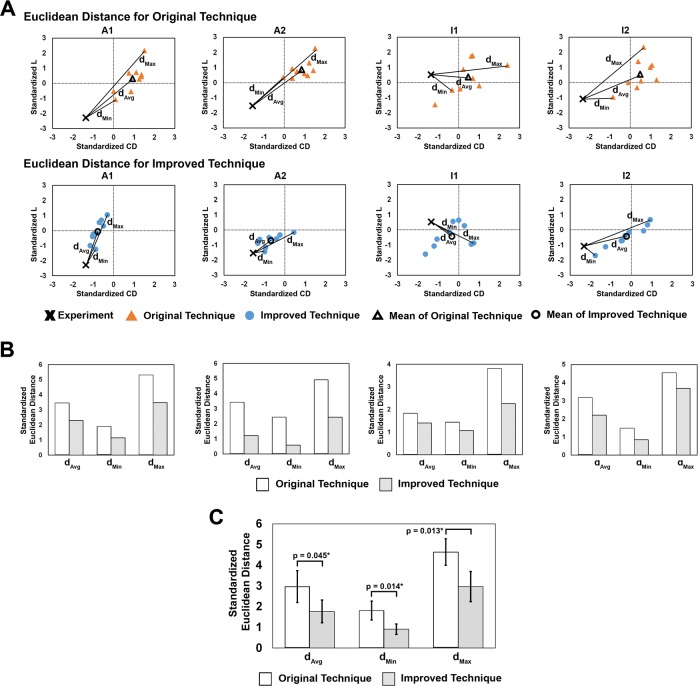
Methods: We previously modeled coils using a pre-shape based on mathematical curves and mechanical properties based on those of platinum wires. In the improved version, to better represent the physical properties of coils, we model coil pre-shapes based on how they are manufactured, and their mechanical properties based on their spring-like geometric structures. To enhance the deployment mechanics, we include coil advancement to the aneurysm in FEM simulations. To test if these new strategies produce more accurate coil deployments, we fabricated silicone phantoms of 2 patient-specific aneurysms in duplicate, deployed coils in each, and quantified coil distributions from intra-aneurysmal cross-sections using coil density (CD) and lacunarity (L). These deployments were simulated 9 times each using the original and improved techniques, and CD and L were calculated for cross-sections matching those in the experiments. To compare the 2 simulation techniques, Euclidean distances (dMin, dMax, and dAvg) between experimental and simulation points in standardized CD-L space were evaluated. Univariate tests were performed to determine if these distances were significantly different between the 2 simulations.

Results: Coil deployments using the improved technique agreed better with experiments than the original technique. All dMin, dMax, and dAvg values were smaller for the improved technique, and the average values across all simulations for the improved technique were significantly smaller than those from the original technique (dMin: p = 0.014, dMax: p = 0.013, dAvg: p = 0.045).

Conclusion: Incorporating coil-specific physical properties and mechanics improves accuracy of FEM simulations of endovascular intracranial aneurysm coiling.


Conflict of interest statement

I have read the journal's policy and the authors of this manuscript have the following competing interests: RJD – None; VMT – Co-founder: Neurovascular Diagnostics, Inc.; SRL – None; NP – None; GFD – None; JMD – Stock/Stock Options: Rist Neurovascular, Inc.; Consultancy: Cerevenous, Medtronic; Payment for Lectures Including Service on Speakers Bureaus: Penumbra; AHS – Financial Interest/Investor/Stock Options/Ownership: Amnis Therapeutics, Apama Medical, BlinkTBI, Inc, Buffalo Technology Partners, Inc., Cardinal Health, Cerebrotech Medical Systems, Inc, Claret Medical, Cognition Medical, Endostream Medical, Ltd, Imperative Care, International Medical Distribution Partners, Rebound Therapeutics Corp., Silk Road Medical, StimMed, Synchron, Three Rivers Medical, Inc., Viseon Spine, Inc. Consultant/Advisory Board: Amnis Therapeutics, Boston Scientific, Canon Medical Systems USA, Inc., Cerebrotech Medical Systems, Inc., Cerenovus, Claret Medical, Corindus, Inc., Endostream Medical, Ltd, Guidepoint Global Consulting, Imperative Care, Integra, Medtronic, MicroVention, Northwest University – DSMB Chair for HEAT Trial, Penumbra, Rapid Medical, Rebound Therapeutics Corp., Silk Road Medical, StimMed, Stryker, Three Rivers Medical, Inc., VasSol, W.L. Gore & Associates. National PI/Steering Committees: Cerenovus LARGE Trial and ARISE II Trial, Medtronic SWIFT PRIME and SWIFT DIRECT Trials, MicroVention FRED Trial & CONFIDENCE Study, MUSC POSITIVE Trial, Penumbra 3D Separator Trial, COMPASS Trial, INVEST Trial. HM – Co-founder: Neurovascular Diagnostics, Inc. This does not alter our adherence to PLOS ONE policies on sharing data and materials.

Figures

Fig 1
Fig 1. The physical properties of coils and how they were modeled.
Top Row: The coil’s primary stock wire is composed of platinum and was not modeled in either technique. 2nd Row: The coil’s secondary structure comprises the stock wire wound to form a helical spring-like structure. The secondary structure was modeled as a series of beam elements in both techniques, with the Improved Technique using hollow elements and the Original using solid elements. 3rd Row: The coils tertiary “pre-shape” is created when the spring-like structure is wound around a mandrel and heat-treated to create a 3D shape with “shape-memory”. The Original Technique modeled the pre-shape as mathematical curves generated from parametric equations, while the Improved Technique modeled the pre-shape by virtually winding the coil’s secondary structure around a mandrel. Bottom Row: We modeled coil mechanical properties after springs, with the Original Technique assuming beam elements had the elastic moduli of a platinum wire and the Improved Technique calculating beam properties by equating beam rigidity to spring rigidity.
Fig 2
Fig 2. Workflow for virtual coil deployment using FEM.
The workflow consists of (A) pre-processing, and (B) FEM simulation. The major improvements (underlined) are in step 3, Coil Model Creation (pre-shape and mechanical properties), and in step 5, Coil Advancement (previously not modeled but now added to capture coil mechanics in tortuous vessels).
Fig 3
Fig 3. Flowchart of our experimental approach.
From Left to Right, computer models of 2 IAs were used in this study as testbeds. Experiment: Based on the IA models, 4 silicone phantoms (duplicates of each IA) were fabricated, coils were deployed into each phantom, and intra-aneurysmal cross-sections were extracted. Simulation: The phantoms were imaged to create virtual models, and coil deployments were virtually recreated using the Original Technique and Improved Technique (9 iterations for each phantom). Cross-sections were extracted matching those in the experiments. Coil Distribution Analysis: Physical and virtual coil distributions were quantified by coil density (CD, space occupied by coil–in red in left image) and lacunarity (L, gaps between coils–red in right image) from cross-section images. To compare the virtual techniques against experiments, Euclidean distances from the experimental coil distributions to the virtual coil distributions were calculated and evaluated (Coil Distribution Analysis).
Fig 4
Fig 4. The 3 mechanical steps of virtual coiling.
(A) Coil Packaging: The coil, in its pre-shape configuration, was pulled continuously into the proximal end of the catheter until it was straightened (red dot = distal tip of the coil). (B) Coil Advancement: The coil was continuously pushed in the catheter (positioned at the parent artery centerline) until it reached the IA. (C) Coil Deployment (Improved Technique): The beginning of coil deployment happens directly after advancement (same geometry in the “box”). For both C and D, the coil was continuously pushed along the catheter into the IA sac until it was completely deployed, ending the FEM simulation. The stable time increment was approximately Δt = 3 μs throughout the simulation of the 3 mechanical steps. (D) Coil Deployment (Original Technique): Coil deployment by the Original Technique occurs without advancement through the catheter, only occurring at the neck of the IA. As shown in the DSA image, the Improved Technique better resembled coil deployment in the actual IA than the Original Technique.
Fig 5
Fig 5. Coil packaging and deployment in experiment and simulation.
(A) Coil packaging is the dynamic process in which the coil is pulled into the catheter from its pre-shape. Qualitatively, the packaging simulation by the Improved Technique better resembles the experiment than the packaging by the Original Technique. However, it should be noted that gravity was not considered in simulations. (B) An example of coil deployment is shown in physical and virtual Phantoms I2. Catheter placement and coil advancement by the Improved Technique resembles the experiment more than the Original Technique.
Fig 6
Fig 6. Quantification of coil experimental and computational results on cross-sections in aneurysm Phantoms A1, A2, I1, and I2.
The binarized image of each experimental cross-section is shown in its corresponding graph. Graphs labeled P1-P5 show the raw values for lacunarity (L—vertical axis) vs. coil density (CD—horizontal axis) measured on each phantom cross-section (1–5), whereby experimental points are shown by a cross, and individual virtual coil deployments are represented by circles (Original) or triangles (Improved). The mean of the virtual coiling results (9 realizations by each technique) are represented by hollow circles (Original) or hollow triangles (Improved). Note that the upper bounds of the vertical and horizontal axes of each graph differ in order to fit the data points tidily in each graph. We observed that in all cross-sections, the range of both virtual coiling techniques lies near the experiment point. Furthermore, in the majority of cross-sections, the mean of the Improved Technique was closer to the experiment than the mean of the Original Technique.
Fig 7
Fig 7. Euclidian distances from experimental to computational results of both techniques in the standardized, aneurysm-averaged CD-L plane.
(A) Example of the 3 Euclidean distances evaluated for comparison of both FEM techniques in the 4 phantoms, namely dAvg, DMin, and dMax. Graph axes represent “standard deviations”, where the origin (0,0) is the mean of standardized CD and L. (B) Bar graphs of the 3 standardized Euclidean distances calculated for both techniques in the 4 phantoms. In all 4 phantoms, dAvg, dMin, and dMax were smaller for the Improved Technique than for the Original Technique. (C) Results of the univariate tests to compare Euclidean distances between techniques across the 4 phantoms. The average dAvg, dMin, and dMax in the Improved Technique had significantly smaller Euclidean distance than the average distance in the Original Technique (significance indicated by asterisk and the p-values for each test are reported).
Fig 8
Fig 8. Average simulation times of the 9 virtual deployments by each FEM technique.
In all 4 phantoms, the average simulation time of the Improved Technique was smaller than for the average time of the Original Technique.

References

    1. Ferns SP, Sprengers ME, van Rooij WJ, Rinkel GJ, van Rijn JC, Bipat S, et al. Coiling of intracranial aneurysms: a systematic review on initial occlusion and reopening and retreatment rates. Stroke; a journal of cerebral circulation. 2009;40(8):e523–9. 10.1161/STROKEAHA.109.553099 . - DOI - PubMed
    1. Molyneux AJ, Kerr RS, Yu LM, Clarke M, Sneade M, Yarnold JA, et al. International subarachnoid aneurysm trial (ISAT) of neurosurgical clipping versus endovascular coiling in 2143 patients with ruptured intracranial aneurysms: a randomised comparison of effects on survival, dependency, seizures, rebleeding, subgroups, and aneurysm occlusion. Lancet. 2005;366(9488):809–17. 10.1016/S0140-6736(05)67214-5 . - DOI - PubMed
    1. Damiano RJ, Ma D, Xiang J, Siddiqui AH, Snyder KV, Meng H. Finite element modeling of endovascular coiling and flow diversion enables hemodynamic prediction of complex treatment strategies for intracranial aneurysm. Journal of biomechanics. 2015;48(12):3332–40. 10.1016/j.jbiomech.2015.06.018 . - DOI - PMC - PubMed
    1. Babiker MH, Chong B, Gonzalez LF, Cheema S, Frakes DH. Finite element modeling of embolic coil deployment: multifactor characterization of treatment effects on cerebral aneurysm hemodynamics. Journal of biomechanics. 2013;46(16):2809–16. 10.1016/j.jbiomech.2013.08.021 . - DOI - PubMed
    1. Otani T, Ii S, Shigematsu T, Fujinaka T, Hirata M, Ozaki T, et al. Computational model of coil placement in cerebral aneurysm with using realistic coil properties. Journal of Biomechanical Science and Engineering. 2015;10(4):15-00555-15-. 10.1299/jbse.15-00555 - DOI

Publication types