

Utility of Centrifugation-Controlled Convective (C3) Flow for Rapid On-chip ELISA
- PMID: 31882905
- PMCID: PMC6934823
- DOI: 10.1038/s41598-019-56772-6
Utility of Centrifugation-Controlled Convective (C3) Flow for Rapid On-chip ELISA
Abstract
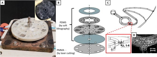
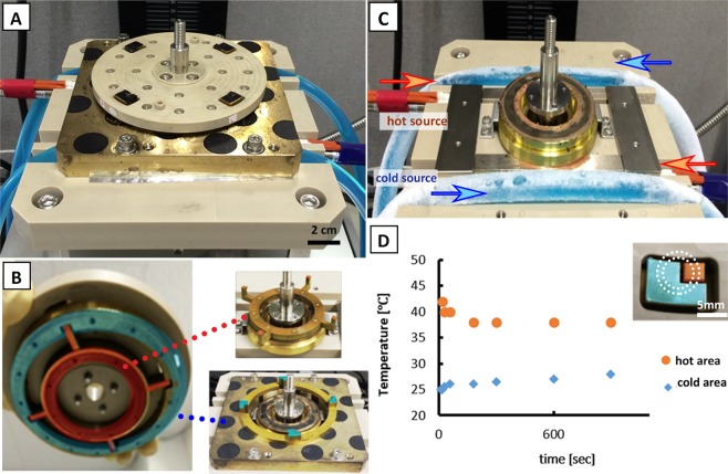
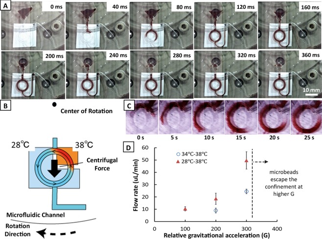
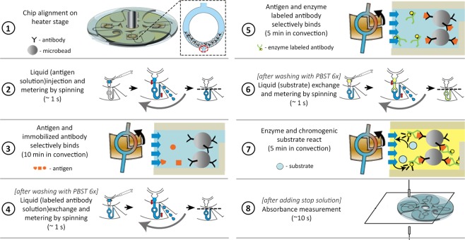
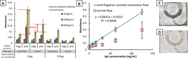
Miniaturizing the enzyme-linked immunosorbent assay (ELISA) protocols in microfluidics is sought after by researchers for a rapid, high throughput screening, on-site diagnosis, and ease in operation for detection and quantification of biomarkers. Herein, we report the use of the centrifugation-controlled convective (C3) flow as an alternative method in fluid flow control in a ring-structured channel for enhanced on-chip ELISA. A system that consists of a rotating heater stage and a microfluidic disk chip has been developed and demonstrated to detect IgA. The ring-structured channel was partially filled with microbeads (250 µm in diameter) carrying the capture antibodies and the analyte solution was driven by thermal convection flow (50 µL/min) to promote the reaction. The remaining part of the circular channel without microbeads served as the observation area to measure the absorbance value of the labeled protein. Currently, the system is capable of conducting four reactions in parallel and can be performed within 30 min at 300 G. A detection limit of 6.16 ng/mL using 24 µL of target sample (IgA) was observed. By simply changing the capture antibodies, the system is expected to be versatile for other immunoassays.
Conflict of interest statement
The authors declare no competing interests.
Figures
Similar articles
-
Rapid, automated, parallel quantitative immunoassays using highly integrated microfluidics and AlphaLISA.Sci Rep. 2015 Jun 15;5:11339. doi: 10.1038/srep11339. Sci Rep. 2015. PMID: 26074253 Free PMC article.
-
Rapid detection of clenbuterol in milk using microfluidic paper-based ELISA.Food Chem. 2018 Apr 25;246:437-441. doi: 10.1016/j.foodchem.2017.12.022. Epub 2017 Dec 7. Food Chem. 2018. PMID: 29291870
-
Gravity-induced convective flow in microfluidic systems: electrochemical characterization and application to enzyme-linked immunosorbent assay tests.Electrophoresis. 2004 Nov;25(21-22):3761-8. doi: 10.1002/elps.200406093. Electrophoresis. 2004. PMID: 15565685
-
Centrifugation-Controlled Thermal Convection and Its Application to Rapid Microfluidic Polymerase Chain Reaction Devices.Anal Chem. 2017 Dec 5;89(23):12797-12804. doi: 10.1021/acs.analchem.7b03107. Epub 2017 Nov 17. Anal Chem. 2017. PMID: 29111686
-
Microfluidic Adapter Converting a 96-Well Cartridge into an Autonomous Microfluidic Device.Anal Chem. 2019 Feb 19;91(4):2686-2694. doi: 10.1021/acs.analchem.8b04043. Epub 2019 Jan 11. Anal Chem. 2019. PMID: 30596424
Cited by
-
Deskilled and Rapid Drug-Resistant Gene Detection by Centrifugal Force-Assisted Thermal Convection PCR Device.Sensors (Basel). 2021 Feb 9;21(4):1225. doi: 10.3390/s21041225. Sensors (Basel). 2021. PMID: 33572363 Free PMC article.
References
-
- Lo R. Microfluidics technology: future prospects for molecular diagnostics. Adv. Heal. Care Technol. 2017;3:3–17. doi: 10.2147/AHCT.S94024. - DOI
-
- Crowther, J. R. The ELISA Guidebook. 516 (Humana Press, 2009).
-
- Eteshola E, Leckband D. Development and characterization of an ELISA assay in PDMS microfluidic channels. Sensors Actuators B Chem. 2001;72:129–133. doi: 10.1016/S0925-4005(00)00640-7. - DOI
Publication types
MeSH terms
LinkOut - more resources
Full Text Sources
Miscellaneous
