Review
. 2019 Dec 26;11(1):34.
doi: 10.3390/mi11010034.

Advances in Magnetoresistive Biosensors

Affiliations
Review

Advances in Magnetoresistive Biosensors

Diqing Su et al. Micromachines (Basel). .

Abstract

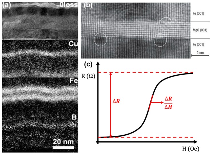
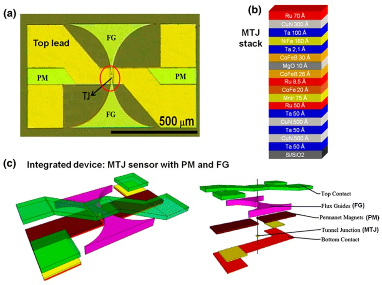
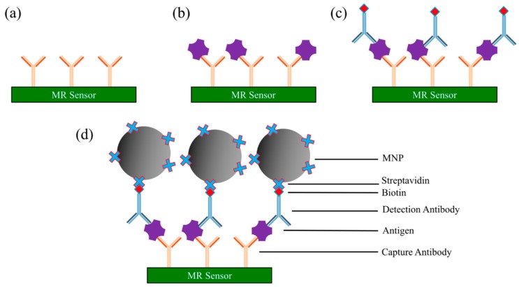
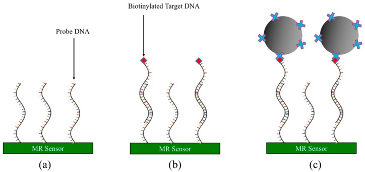
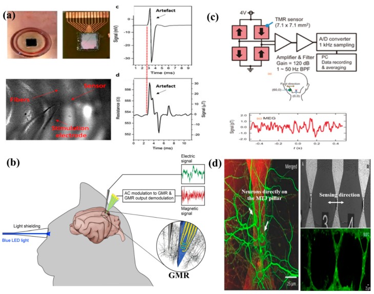
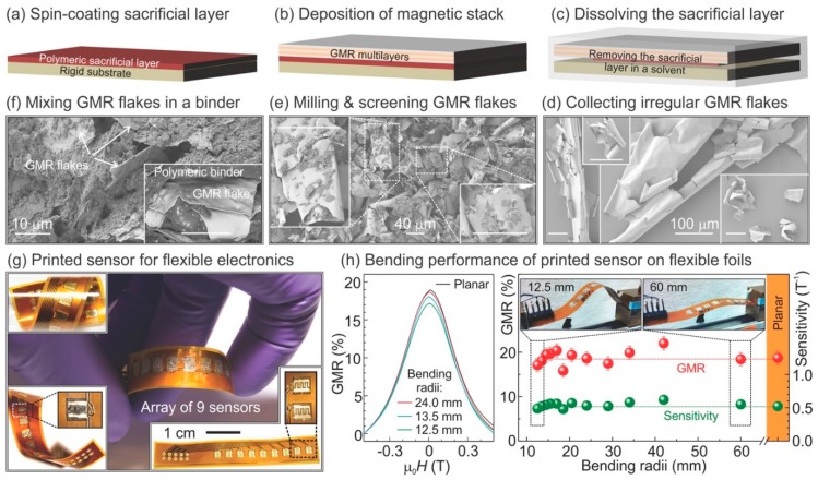
Magnetoresistance (MR) based biosensors are considered promising candidates for the detection of magnetic nanoparticles (MNPs) as biomarkers and the biomagnetic fields. MR biosensors have been widely used in the detection of proteins, DNAs, as well as the mapping of cardiovascular and brain signals. In this review, we firstly introduce three different MR devices from the fundamental perspectives, followed by the fabrication and surface modification of the MR sensors. The sensitivity of the MR sensors can be improved by optimizing the sensing geometry, engineering the magnetic bioassays on the sensor surface, and integrating the sensors with magnetic flux concentrators and microfluidic channels. Different kinds of MR-based bioassays are also introduced. Subsequently, the research on MR biosensors for the detection of protein biomarkers and genotyping is reviewed. As a more recent application, brain mapping based on MR sensors is summarized in a separate section with the discussion of both the potential benefits and challenges in this new field. Finally, the integration of MR biosensors with flexible substrates is reviewed, with the emphasis on the fabrication techniques to obtain highly shapeable devices while maintaining comparable performance to their rigid counterparts.

Keywords: MNPs; biosensors; brain mapping; flexible devices; genotyping; immunoassay; magnetoresistance.


Conflict of interest statement

The authors declare no conflict of interest.

Figures

Figure 1
Figure 1
Schematic illustration of different types of magnetoresistance (MR) sensors and their applications. Reprinted from Ref. [3,5,22,23] with the permission from Elsevier 2019, 2017, 2018, and 2018, respectively.
Figure 2
Figure 2
(a) Energy filtered TEM image of a giant magnetoresistance (GMR) structure of oFe (1.5 nm)/Cu (50 nm)/IrMn (10 nm)/CoFeB (6 nm)/Cu (2.5 nm)/CoFeB (6 nm)/Ru (8 nm) [51]; (b) MgO-based magnetic tunnel junction (MTJ) with 180% tunneling magnetoresistance (TMR) ratio reported by Yuasa et al. [52]; (c) a typical transfer curve of the magnetoresistive sensors. Reprinted with permission from AIP Publishing 2010 (a) and Springer Nature 2004 (b).
Figure 3
Figure 3
(a) Schematic of density of electronic states with parallel magnetization (PM) and antiparallel magnetization (APM). E, the electron energy; EF, the Fermi level; (b) Two-current model of tunneling magnetoresistance.
Figure 4
Figure 4
(a) Top view picture of one MTJ integrated with permanent magnets and MFCs; (b) stack structure of the MTJ devices; (c) final layout of the devices [71]. Reprinted with permission from Springer-Verlag Berlin Heidelberg 2014.
Figure 5
Figure 5
Schematic view of a MR sensor-based sandwich assay. (a) MR sensor surface coated with capture antibodies; (b) biological sample is loaded onto sensor surface, and antigens of interest specifically bind to capture antibodies; (c) biotinylated detection antibodies are added and specifically bind to antigens; (d) streptavidin-linked magnetic nanoparticles (MNPs) are added and bind to detection antibodies through biotin-streptavidin conjugation.
Figure 6
Figure 6
Schematic view of competitive binding assays. (a) MR sensor surface pre-coated with capture antibodies. The MNP-labeled antigens are competing with unlabeled antigens from testing samples for the antibody binding sites; (b) MR sensor surface pre-coated with antigens. The MNP-labeled antibodies are competing with unlabeled antibodies from testing samples for the antigen binding sites.
Figure 7
Figure 7
Schematic view of direct assays. (a) MR sensor surface pre-coated with target antibodies from testing sample followed by adding MNP-linked antigens for specific binding. The number of captured MNPs through antigen-antibody conjugations is proportional to the electrical/magnetic signals from MR sensors; (b) MR sensor surface pre-coated with target antigens from testing sample followed by adding MNP-linked antibodies; (c) MR sensor surface pre-coated with biotin followed by adding streptavidin-coated MNPs. This structure is mostly used as a positive control.
Figure 8
Figure 8
Schematic view of DNA-based assay. (a) Probe DNA strands immobilized onto MR sensor surface; (b) biotinylated target DNA hybridizes with probe DNA; (c) streptavidin-coated MNPs captured by target DNAs through biotin-streptavidin conjugation.
Figure 9
Figure 9
(a) The GMR handheld system can communicate with cell phones, laptops, tablets, and computers from Ref. [64]; (b) layout of the handheld system with the cartridge shell and electrical interface in Ref. [64]; (c) the Eigen Diagnosis Platforms (EDP) system from Ref. [20]; (d) the block diagram of the test process of the EDP system in Ref. [20]. The straightforward interface and process can lead users through the testing process and the results can be shown 10 min after the sample addition. Reprinted with permission from American Chemical Society 2017.
Figure 10
Figure 10
Resistance change of MTJ sensor after binding with three different concentrations of alpha-fetoprotein (AFP) antigens [114]. Reprinted with permission from AIP Publishing 2012.
Figure 11
Figure 11
Schematic structure of the magnetic immuno-chromatographic test strip [12]. Reprinted with permission from Elsevier 2019.
Figure 12
Figure 12
TMR biosensor signal response to the aggregated magnetic particles on T line with different concentrations of ricin [12]. Reprinted with permission from Elsevier 2019.
Figure 13
Figure 13
(a) The fabrication steps of the disposable SPA card and immobilization of DNA with magnetic labels as the biomarkers [119]; (b) the AMR sensor output with varying concentration of the MNPs and representing the lowest detectable amount of MNPs is 312 ng [119]; (c) the optical microscopic image of the fabricated Wheatstone Bridge AMR sensors with a single resistor (S1), three resistors in series (S3), five resistors in series (S5), and six resistors in series and parallel configuration (SP6) [120]; (d) magnetoresistance (in mV) and sensitivity (in mV/Oe) dependence on magnetic field for the designed S1, S3, and SP6 patterns [120]. (a,b) Reprinted under the terms of the Creative Commons Attribution 3.0 license. (c,d) Reprinted with permission from The Minerals, Metals & Materials Society 2018.
Figure 14
Figure 14
(a) The firing of neurons causes an ionic current to flow which according to the Biot-Savart Law generates a magnetic field (B) around the neurons that can be measured by magnetic sensors [143]; (b) the first recording of the magnetic field picked up from a single neuron with the help of a toroidal pick-up coil as reported by Roth and Wikswo [130]; (c) Superconducting Quantum Interference Devices (SQUID) system set up to record magnetic field from the cerebral cortex of the human brain. The circular insets show the real-time magnetic field recording from the brain [132]. (a) Reprinted under the terms of the Creative Commons Attribution 4.0 International License (CC BY). (b) Reprinted with permission from Elsevier 1985. (c) Reprinted with permission from IOP Publishing 1989.
Figure 15
Figure 15
(a) The SV-GMR sensor stack arranged in an array of 15 sensors, each of 3 × 15 µm2 in cross-section. The R-H curves shows that it is a linear sensor having an MR ratio of 7.8% and a sensitivity of 0.15%/Oe [138]; (b) in vitro system set-up for recording neural response from mice hippocampal slices [139]; (c) the real-time neural response as recorded from the SV-GMR sensor array [138]; (d) GMR sensor recording from the hippocampal slices with (bottom) and without (top) the addition of the tetrodotoxin (TTX) drug, which blocks neural response [138]. Reprinted with permission from AIP Publishing 2011.
Figure 16
Figure 16
(a) MTJ sensor array and the in vitro experimental set-up demonstrating the neural response. The signal (in mV) and the resistance (in Ω) are the local field potential (LFP) recordings and MTJ signal response, respectively. The shape of both the signal resembles each other [141]; (b) in vivo experimental set-up to record neural response from rat cerebral cortex [140]; (c) Four TMR sensors arranged in Wheatstone Bridge configuration along with neural response as recorded by the sensor configuration (in pT) [142]. (a) Reprinted under a Creative Commons Attribution (CC BY) license. (b) Reprinted with permission from Elsevier 2017. (c) Reprinted under the terms of the Creative Commons Attribution 4.0 license. (d) Orientation of the axons of the neurons perpendicular to the sensing direction of the MTJ pillars to facilitate most optimized detection of the magnetic field generated by the ionic currents flowing through the axons [67].
Figure 17
Figure 17
(af) Schematic illustration of the fabrication process of the GMR flakes; (g) printed GMR sensor arrays on flexible substrate; (h) evolution of magnetoelectrical performance of the printed GMR sensors upon different bending radius [151]. Reprinted under the terms of the Creative Commons Attribution Non-Commercial License.

Similar articles

Cited by

References

    1. Tsang C.H., Fontana R.E., Lin T., Heim D.E., Gurney B.A., Williams M.L. Design, fabrication, and performance of spin-valve read heads for magnetic recording applications. IBM J. Res. Dev. 1998;42:103–116. doi: 10.1147/rd.421.0103. - DOI
    1. Makarov A., Windbacher T., Sverdlov V., Selberherr S. CMOS-compatible spintronic devices: A review. Semicond. Sci. Technol. 2016;31:11. doi: 10.1088/0268-1242/31/11/113006. - DOI
    1. Borole U.P., Subramaniam S., Kulkarni I.R., Saravanan P., Barshilia H.C., Chowdhury P. Highly sensitive giant magnetoresistance (GMR) based ultra low differential pressure sensor. Sens. Actuators A-Phys. 2018;280:125–131. doi: 10.1016/j.sna.2018.07.022. - DOI
    1. Park J.J., Reddy K.S.M., Stadler B., Flatau A. Magnetostrictive Fe-Ga/Cu nanowires array with GMR sensor for sensing applied pressure. IEEE Sens. J. 2017;17:2015–2020. doi: 10.1109/JSEN.2017.2657789. - DOI
    1. Ouyang Y., Wang Z.X., Zhao G., Hu J., Ji S.J., He P.N., Wang S.X. Current sensors based on GMR effect for smart grid applications. Sens. Actuators A-Phys. 2019;294:8–16. doi: 10.1016/j.sna.2019.05.002. - DOI