Review
. 2019 Nov 11:2019:3018568.
doi: 10.34133/2019/3018568. eCollection 2019.

A Review of Printable Flexible and Stretchable Tactile Sensors

Affiliations
Review

A Review of Printable Flexible and Stretchable Tactile Sensors

Kirthika Senthil Kumar et al. Research (Wash D C). .

Abstract

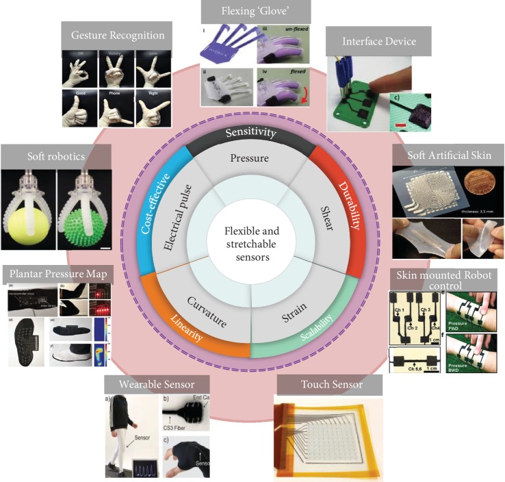
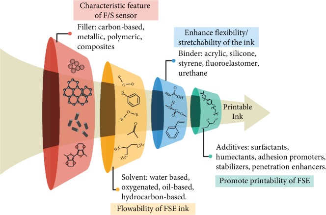
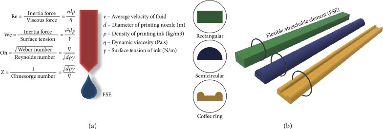
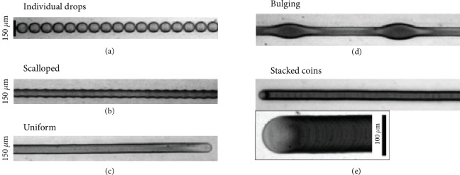
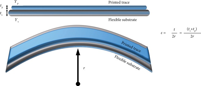
Flexible and stretchable tactile sensors that are printable, nonplanar, and dynamically morphing are emerging to enable proprioceptive interactions with the unstructured surrounding environment. Owing to its varied range of applications in the field of wearable electronics, soft robotics, human-machine interaction, and biomedical devices, it is required of these sensors to be flexible and stretchable conforming to the arbitrary surfaces of their stiff counterparts. The challenges in maintaining the fundamental features of these sensors, such as flexibility, sensitivity, repeatability, linearity, and durability, are tackled by the progress in the fabrication techniques and customization of the material properties. This review is aimed at summarizing the recent progress of rapid prototyping of sensors, printable material preparation, required printing properties, flexible and stretchable mechanisms, and promising applications and highlights challenges and opportunities in this research paradigm.


Conflict of interest statement

The authors declare no conflicts of interest.

Figures

Figure 1
Figure 1
Rapid prototyping methods, their advantages, and the applications of recently developed tactile sensors. “Flexing ‘Glove'” [217], reproduced with permission. Copyright PLOS, 2012. “Interface Device” [217], reproduced with permission. Copyright PLOS, 2012. “Soft Artificial Skin” [218], reproduced with permission. Copyright IEEE, 2012. “Skin mounted Robot control” [219], reproduced with permission. Copyright John Wiley and Sons, 2014. “Touch Sensor” [220], reproduced with permission. Copyright American Chemical Society, 2015. “Wearable Sensor” [39], reproduced with permission. Copyright John Wiley and Sons, 2015. “Plantar Pressure Map” [109], reproduced with permission. Copyright John Wiley and Sons, 2017. “Soft robotics” [40], reproduced with permission. Copyright John Wiley and Sons, 2018. “Gesture Recognition” [105], reproduced with permission. Copyright Royal Society of Chemistry, 2016.
Figure 2
Figure 2
Schematic illustration of flexible (F) and stretchable (S) printed elements. The dotted lines represent the neutral line. (a) Flexibility defined as the bendability and the deflecting ability of the sensor from the plane with a radius of curvature, R. Y represents the deflection of the sensor from the neutral line. (b) The longitudinal strain caused by stretching increases the length of the printed FSE along the direction of load, while the lateral strain caused by stretching decreases the dimension perpendicular to the direction of load.
Figure 3
Figure 3
The different phases in the fabrication of printable flexible/stretchable tactile sensors.
Figure 4
Figure 4
(a) Schematic illustration of the multicore-shell fiber printing process of capacitive strain sensors in a four-layer configuration. (b, c) The conductive and elastomeric inks are loaded into separate reservoirs. (d) Illustrations of the outlet region where the printing simultaneously forms the multicore-shell. (e) Magnified optical image of the printed multicore-shell segmented view. (f) Two fully printed capacitive strain sensors [39]. Reproduced with permission. Copyright John Wiley and Sons, 2015.
Figure 5
Figure 5
The fabrication steps of the embedded 3D printing of actuators innervated with sensors [40]. Reproduced with permission. Copyright John Wiley and Sons, 2018.
Figure 6
Figure 6
Typical components required for the formulation of a printable ink and the significance of their role [221].
Figure 7
Figure 7
Important printability properties required for appropriate FSE printed trace. (a) Performance parameters of the droplet formation process. Reynolds number (Re), Weber number (We), and Ohnesorge number (Oh) together help to characterize Z, which helps determine the suitability of fluid for printing 1 < Z < 10, considered to be the optimal range of stable droplet formation [57]. (b) Various cross-section profiles of the printed trace depending on the viscosity of the inks.
Figure 8
Figure 8
Different morphologies of the printed pattern with varied droplet spacing [66].
Figure 9
Figure 9
Mechanics of a flexible substrate and strain induced on its surface.
Figure 10
Figure 10
Various strategies to make the sensor stretchable placed according to their maximum elongations. Composites: CNT based [98] and silver nanostructures based [115]. 3-dimensional structures: helical [222], crack induced [223], and out of plane buckling [224]. Inplane structures: horseshoe [225], zig-zag [226], serpentine [227], and self-similar serpentine [94]. Stretchable materials: graphene [228], PDMS [229], EGaIn [230], and Ecoflex 00-30 [229].
Figure 11
Figure 11
The wetting behavior of the ink droplet on the substrate. (a) θ is the contact angle between the printed drop and the substrate. (b) For higher θ values, the surface tension on the droplet dominates the engaging forces on the surface and it is more difficult to bond to the substrate.
Figure 12
Figure 12
Printed flexible/stretchable piezoresistive pressure sensor. (a) Schematic illustration of the piezoresistive transduction principle. (b) Printed stretchable tactile sensor with the multimaterial fabrication: (A) schematic of different layers of a tactile sensor; (B) 8 sequential steps of the 3D printing process [231]. Reproduced with permission. Copyright John Wiley and Sons, 2017. (c) Direct printing of nanocomposite printable inks for piezoresistive sensor applications [232]. Reproduced with permission. Copyright John Wiley and Sons, 2018.
Figure 13
Figure 13
Printed flexible/stretchable piezoelectric pressure sensor. (a) Schematic illustration of the piezoelectric transduction principle. (b) Step by step fabrication of PVDF fibers deposited on the 3D printed wavy substrates to produce the self-powered pressure sensor [100]. Reproduced with permission. Copyright Springer Nature, 2017.
Figure 14
Figure 14
Printed flexible/stretchable piezocapacitive pressure sensor. (a) Schematic illustration of the piezocapacitive transduction principle. (b) Microstructured PDMS inkjet printed and sandwiched between ITO-coated glass [198]. Reproduced with permission. Copyright AIP Publishing, 2017. (c) Schematic of the fabrication process of a bimodal e-skin with 4 × 4 pixel sensor and its strain distribution mapping [35]. Reproduced with permission. Copyright John Wiley and Sons, 2019.
Figure 15
Figure 15
Printed flexible/stretchable triboelectric pressure sensor. (a) Schematic illustrations of the triboelectric transduction principles. (b) Fabrication procedure of the ultraflexible triboelectric nanogenerator of different sizes and intricate structure [202]. Reproduced with permission. Copyright Elsevier, 2018.
Figure 16
Figure 16
Printed flexible/stretchable strain sensors. (a) Printing fabrication steps of the piezoresistive strain sensor and its application on the wrist [205]. Reproduced with permission. Copyright American Chemical Society, 2018. (b) Embedded 3D printed strain sensor and its application as a glove [41]. Reproduced with permission. Copyright John Wiley and Sons, 2014. (c) Liquid metal alloy EGaIn printed and encapsulated to perform as a strain sensor to detect the elbow flexion and extension [207]. Reproduced with permission. Copyright IEEE, 2018.
Figure 17
Figure 17
Highlights of the promising applications of printable flexible/stretchable tactile sensors. (a) Soft robotic grippers innervated with sensors grasp objects of various size, shape, surface, and temperature [40]. Reproduced with permission. Copyright John Wiley and Sons, 2018. (b) Detection of human motion under the applied strain and remote control of the robotic finger [149]. Reproduced with permission. Copyright American Chemical Society, 2018. (c) The stretchable piezoresistive array for various applications, such as transfer of cup using the control of the robotic arm, shape detection of an arrow-shaped object, and application in the chess game and as a stretchable gaming pad console [212]. Reproduced with permission. Copyright John Wiley and Sons, 2018.

References

    1. Ma Z., Li S., Wang H., et al. Advanced electronic skin devices for healthcare applications. Journal of Materials Chemistry B. 2019;7(2):173–197. doi: 10.1039/c8tb02862a. - DOI - PubMed
    1. Su R., Park S. H., Li Z., McAlpine M. C. Robotic Systems and Autonomous Platforms. Elsevier; 2019.
    1. Al Moubayed S., Beskow J., Skantze G., Granström B. Cognitive Behavioural Systems. Springer; 2012.
    1. Ponraj G., Kirthika S. K., Thakor N. V., Yeow C.-H., Kukreja S. L., Ren H. Development of flexible fabric based tactile sensor for closed loop control of soft robotic actuator. 2017 13th IEEE Conference on Automation Science and Engineering (CASE); 2017; Xi'an, China. pp. 1451–1456. - DOI
    1. Au A. K., Bhattacharjee N., Horowitz L. F., Chang T. C., Folch A. 3D-printed microfluidic automation. Lab on a Chip. 2015;15(8):1934–1941. doi: 10.1039/c5lc00126a. - DOI - PMC - PubMed

LinkOut - more resources