. 2020 Jan 8;11(1):121.
doi: 10.1038/s41467-019-13980-y.

Implementing digital computing with DNA-based switching circuits

Affiliations

Implementing digital computing with DNA-based switching circuits

Fei Wang et al. Nat Commun. .

Abstract

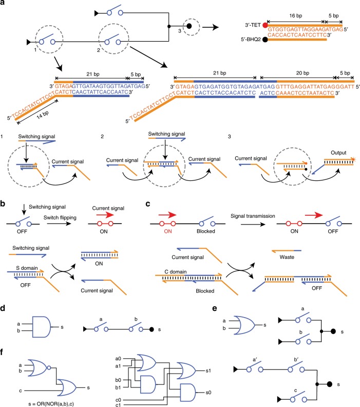
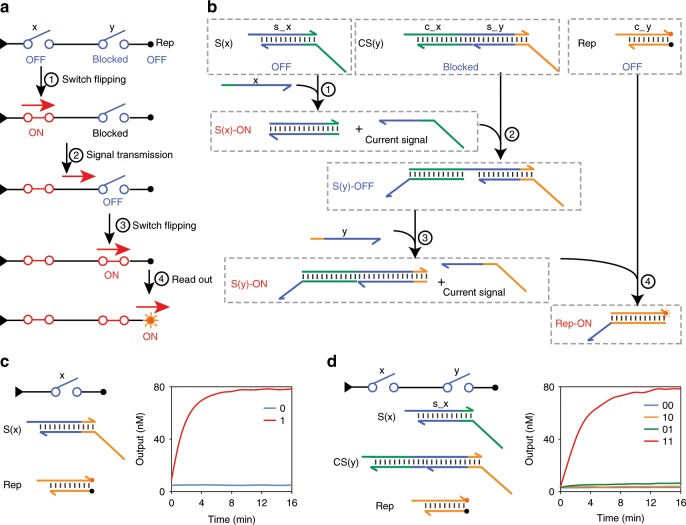
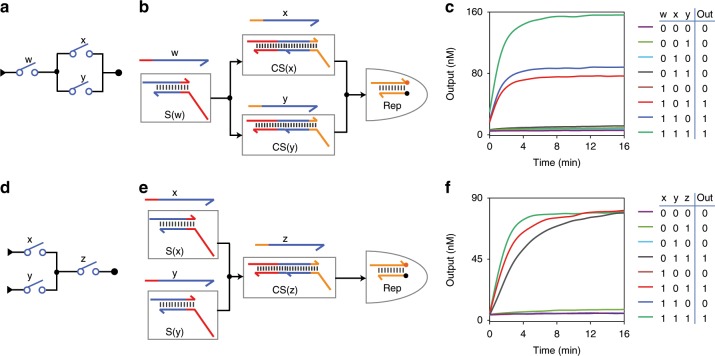
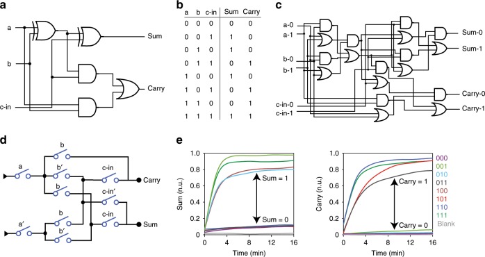
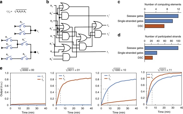
DNA strand displacement reactions (SDRs) provide a set of intelligent toolboxes for developing molecular computation. Whereas SDR-based logic gate circuits have achieved a high level of complexity, the scale-up for practical achievable computational tasks remains a hurdle. Switching circuits that were originally proposed by Shannon in 1938 and nowadays widely used in telecommunication represent an alternative and efficient means to realize fast-speed and high-bandwidth communication. Here we develop SDR-based DNA switching circuits (DSCs) for implementing digital computing. Using a routing strategy on a programmable DNA switch canvas, we show that arbitrary Boolean functions can be represented by DSCs and implemented with molecular switches with high computing speed. We further demonstrate the implementation of full-adder and square-rooting functions using DSCs, which only uses down to 1/4 DNA strands as compared with a dual-rail logic expression-based design. We expect that DSCs provide a design paradigm for digital computation with biomolecules.


Conflict of interest statement

The authors declare no competing interests.

Figures

Fig. 1
Fig. 1. DSC-based implementation of Boolean computation.
a Schematic illustration and molecular details of the DSC system. Typically, a DSC contains three types of elementary molecules: (1) Starting switch that responds to its switching signal. (2) Downstream switch that responds to current signal and switching signal. (3) Reporter that responds to current signal and generates fluorescent output. b Schematic illustration and DNA implementation for switching signal response. c Schematic illustration and DNA implementation for current signal transmission. d AND logic and the corresponding SC. e OR logic and the corresponding SC. f Left: a NOR-OR circuit with NOT operation. Middle: dual-rail representation of the NOR-OR circuit. Right: SC implementation, where a’ and b’ represent the complementary value of a and b, respectively.
Fig. 2
Fig. 2. Experimental implementation of switch flipping and current signal transmission.
a Schematic illustration of signal propagation in a switching circuit with two series switches. b Molecular implementation and chemical reaction network of the circuit in a. c Molecular implementation and fluorescence kinetics data of a single-switch circuit. d Molecular implementation and fluorescence kinetics data of a two-switch circuit. Source data are provided as a Source Data file.
Fig. 3
Fig. 3. Fan-out and fan-in of DNA switches.
ac Switching circuit diagram (a), molecular implementation (b), and fluorescence readout (c) of a circuit with a two-output switch. df Switching circuit diagram (d), molecular implementation (e), and fluorescence readout (f) of a circuit with a two-input switch. Source data are provided as a Source Data file.
Fig. 4
Fig. 4. Implementing arbitrary Boolean functions with DSCs.
a The mapping process from a logic function to a DSC for a three-input voting logic. b DSC for the voting logic in a. c Change in free energy of stepwise switch flipping with each input combination that leads to output. d Experimental fluorescence readout with DSC. e Logic circuit implementation of the voting logic in a. f Change in free energy of stepwise gate opening with each input combination that leads to output. g Experimental fluorescence readout with logic gate implementation. Source data are provided as a Source Data file.
Fig. 5
Fig. 5. Implementing a full-adder with a DSC.
ad Logic gate diagram (a), truth table (b), dual-rail representation (c), and switching circuit diagram (d) of the full-adder circuit. e Fluorescence readout of sum (left) and carry (right) with all possible combinations of inputs. Source data are provided as a Source Data file.
Fig. 6
Fig. 6. A DSC for square-root calculation.
a The DSC used to calculate the square root of a four-bit number. b A dual-rail logic circuit to perform the same square-rooting function. c Number of computing elements using DSC in comparison with previous logic gate circuits with seesaw gates and single-stranded gates. d Number of participated DNA strands using DSC in comparison with previous logic gates implementations. e Experimental computing kinetics with four representative inputs. Source data are provided as a Source Data file.

References

    1. Seelig G, Soloveichik D, Zhang DY, Winfree E. Enzyme-free nucleic acid logic circuits. Science. 2006;314:1585–1588. doi: 10.1126/science.1132493. - DOI - PubMed
    1. Turberfield, A. J. et al. DNA fuel for free-running nanomachines. Phys. Rev. Lett. 90, 118102 (2003). - PubMed
    1. Yurke B, Turberfield AJ, Mills AP, Simmel FC, Neumann JL. A DNA-fuelled molecular machine made of DNA. Nature. 2000;406:605–608. doi: 10.1038/35020524. - DOI - PubMed
    1. Li W, Zhang F, Yan H, Liu Y. DNA based arithmetic function: a half adder based on DNA strand displacement. Nanoscale. 2016;8:3775–3784. doi: 10.1039/C5NR08497K. - DOI - PubMed
    1. Thubagere AJ, et al. Compiler-aided systematic construction of large-scale DNA strand displacement circuits using unpurified components. Nat. Commun. 2017;8:14373. doi: 10.1038/ncomms14373. - DOI - PMC - PubMed

Publication types