. 2020 Jan 14;15(1):e0227372.
doi: 10.1371/journal.pone.0227372. eCollection 2020.

A smartphone-enabled wireless and batteryless implantable blood flow sensor for remote monitoring of prosthetic heart valve function

Affiliations

A smartphone-enabled wireless and batteryless implantable blood flow sensor for remote monitoring of prosthetic heart valve function

Bernhard Vennemann et al. PLoS One. .

Abstract

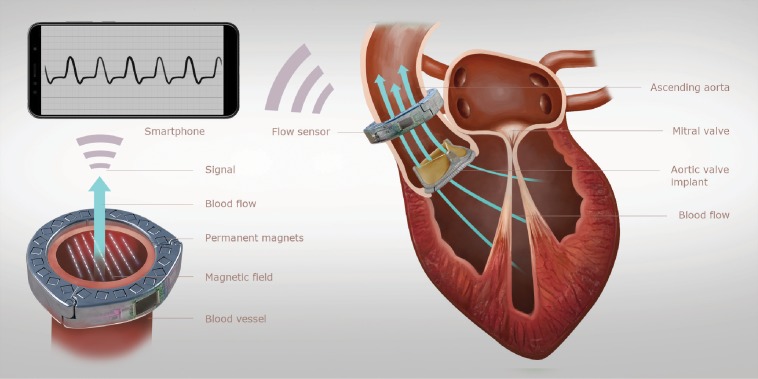
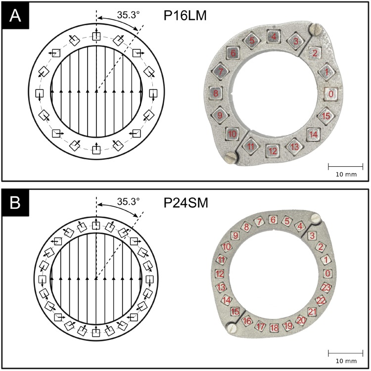
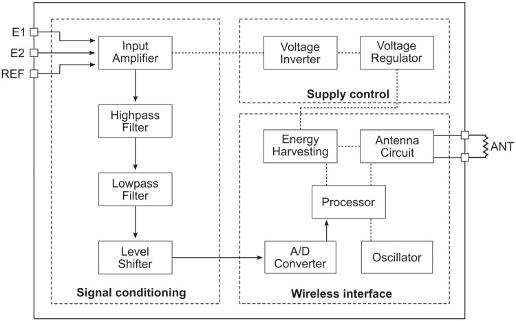
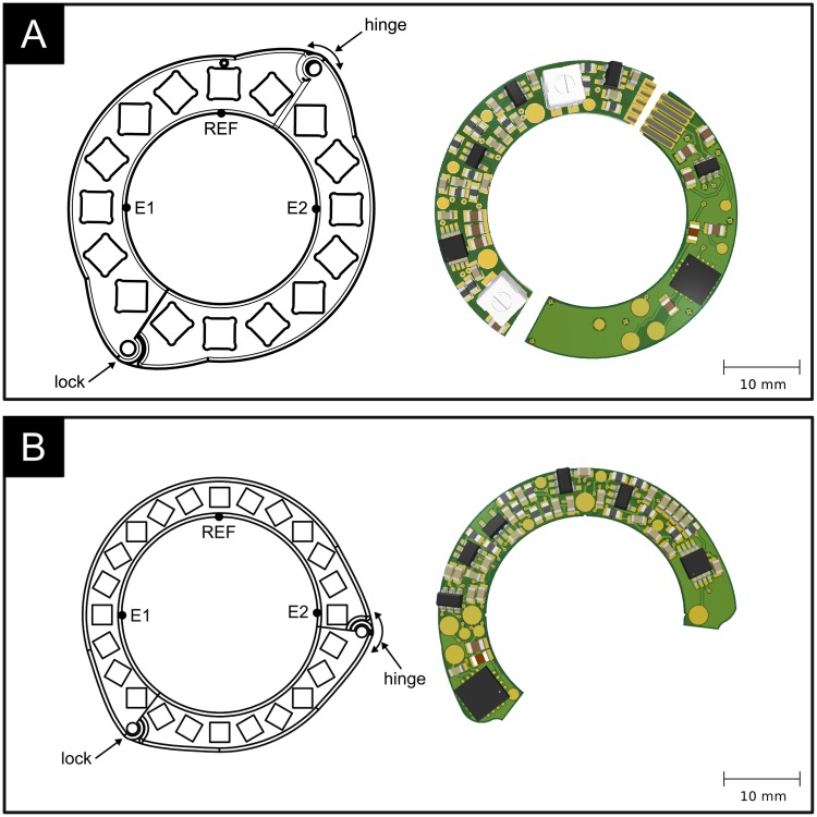
Aortic valve disease is one of the leading forms of complications in the cardiovascular system. The failing native aortic valve is routinely surgically replaced with a bioprosthesis. However, insufficient durability of bioprosthetic heart valves often requires reintervention. Valve degradation can be assessed by an analysis of the blood flow characteristics downstream of the valve. This is cost and labor intensive using clinical methodologies and is performed infrequently. The integration of consumer smartphones and implantable blood flow sensors into the data acquisition chain facilitates remote management of patients that is not limited by access to clinical facilities. This article describes the characteristics of an implantable magnetic blood flow sensor which was optimized for small size and low power consumption to allow for batteryless operation. The data is wirelessly transmitted to the patient's smartphone for in-depth processing. Tests using three different experimental setups confirmed that wireless and batteryless blood flow recording using a magnetic flow meter technique is feasible and that the sensor system is capable of monitoring the characteristic flow downstream of the valve.


Conflict of interest statement

The authors have declared that no competing interests exist.

Figures

Fig 1
Fig 1. Illustration of the heart valve monitoring system.
An implantable magnetic flow sensor attaches to the ascending aorta to measure the characteristic flow profile downstream of the aortic valve. A smartphone wirelessly receives the measurement data and inductively powers the implant.
Fig 2
Fig 2. Design principle of a circular Halbach array.
The angles γ and δ can be computed according to Eqs 2 and 3.
Fig 3
Fig 3. Two prototype Halbach ring implementations.
A: using 16 neodymium magnets of size 4mm x 4mm x 15mm. B: using 24 neodymium magnets of size 2.5mm x 2.5mm x 7.5mm. Inner diameter: 26mm.
Fig 4
Fig 4. Functional block diagram of the electronic circuit.
The circuit comprises three main functional blocks: signal conditioning, wireless interface and supply control. The path of the blood flow signal is indicated by arrows.
Fig 5
Fig 5. Two implementations of the electronic circuitry on a printed circuit board (PCB).
A: using two semicircular PCBs that are fitted onto each half of the magnet array and connected through gold-plated electrical spring contacts. B: using a single PCB and an alternatively segmented magnet ring.
Fig 6
Fig 6. Experimental setup for magnetic field measurements.
A 3-axis Hall sensor is mounted onto a computer-controlled traversing stage allowing to obtain measurements on a finely resolved grid within the magnet ring.
Fig 7
Fig 7. Experimental setup for electronic circuit characterization.
A function generator generates sinusoidal test signals that are fed to the test circuit. Its signal response is recorded using an oscilloscope.
Fig 8
Fig 8. Experimental setup for end-to-end flow sensor testing.
Sinusoidal flow is created using a piston pump. Reference measurements of the piston movement using an LVDT are compared to the smartphone flow recordings to determine the sensor characteristics.
Fig 9
Fig 9. Results of magnetic field simulations and measurements in the center plane.
Contours indicate the vertical magnetic flux density magnitude. Vectors indicate the in-plane magnetic field components. A: result for the 16-magnet prototype (P16LM). B: result for the 24-magnet prototype (P24SM). Gray blocks indicate the electrode positions. Red shaded region illustrates the blood vessel.
Fig 10
Fig 10. Results of transfer function measurement.
Solid line: analytical solution. Circles: measurement values.
Fig 11
Fig 11. Results of flow benchmark measurements.
Results for P16LM are shown in blue, those of P24SM are shown in red. The median signal amplitudes are plotted as dots, and the minimum and maximum measurement values are indicated with error bars to visualize repeatability. The lines depict the best linear fit through the measurement data.
Fig 12
Fig 12. Analysis of effective sample rate.
Histogram of the time between successive samples for the combination of all flow benchmark measurements. The dashed lines indicate the average time between samples and one standard deviation above and below the average.
Fig 13
Fig 13. End-to-end measurement in a physiological flow loop.
A flow loop produces physiological flow (cardiac output: 5 L/min, systolic to diastolic pressure: 120/80 mmHg) and the instantaneous flow rate through the ascending aorta is recorded with the sensor system.

References

    1. Head SJ, Çelik M, Kappetein AP. Mechanical versus bioprosthetic aortic valve replacement. Eur Heart J. 2017. July;38(28):2183–91. 10.1093/eurheartj/ehx141 - DOI - PubMed
    1. Nishimura RA. Aortic Valve Disease. Circulation. 2002. August;106(7):770–2. 10.1161/01.cir.0000027621.26167.5e - DOI - PubMed
    1. Vesely I. The evolution of bioprosthetic heart valve design and its impact on durability. Cardiovasc Pathol. 2003. Sep-Oct;12(5):277–286. 10.1016/s1054-8807(03)00075-9 - DOI - PubMed
    1. Grunkenmeier G, Jamieson W, Miller D, Starr A. Actuarial versus actual risk of porcine structural valve deterioration. J Thorac Cardiovasc Surg. 1994. October;108(4):709–18. 10.1016/S0022-5223(94)70298-5 - DOI - PubMed
    1. Vilkomerson D, Chilipka T. Implantable doppler system for self-monitoring vascular grafts. IEEE Ultrasonics Symposium. 2005 461–5.

MeSH terms