Review
. 2020 Jan 8;10(1):119.
doi: 10.3390/nano10010119.

Fabrication and Plasma Modification of Nanofibrous Tissue Engineering Scaffolds

Affiliations
Review

Fabrication and Plasma Modification of Nanofibrous Tissue Engineering Scaffolds

Mahtab Asadian et al. Nanomaterials (Basel). .

Abstract

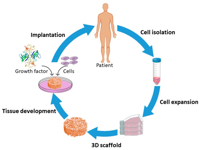
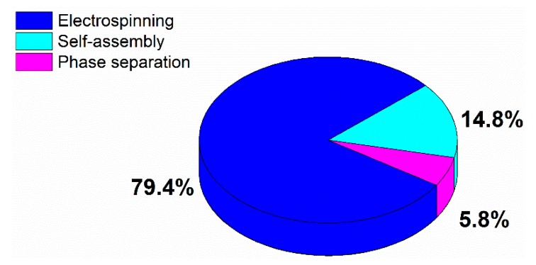
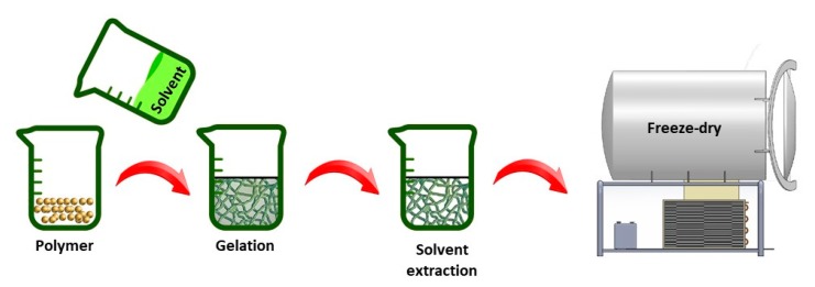
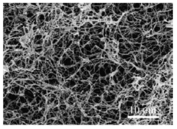
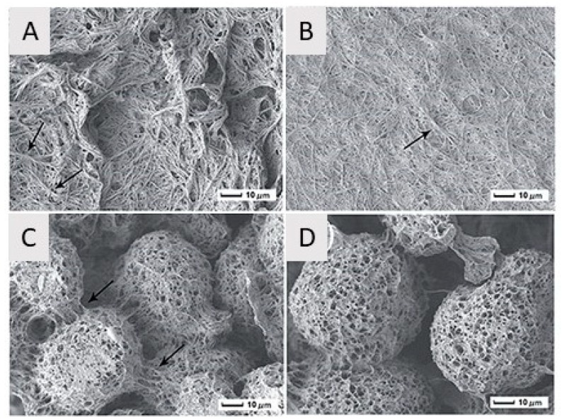
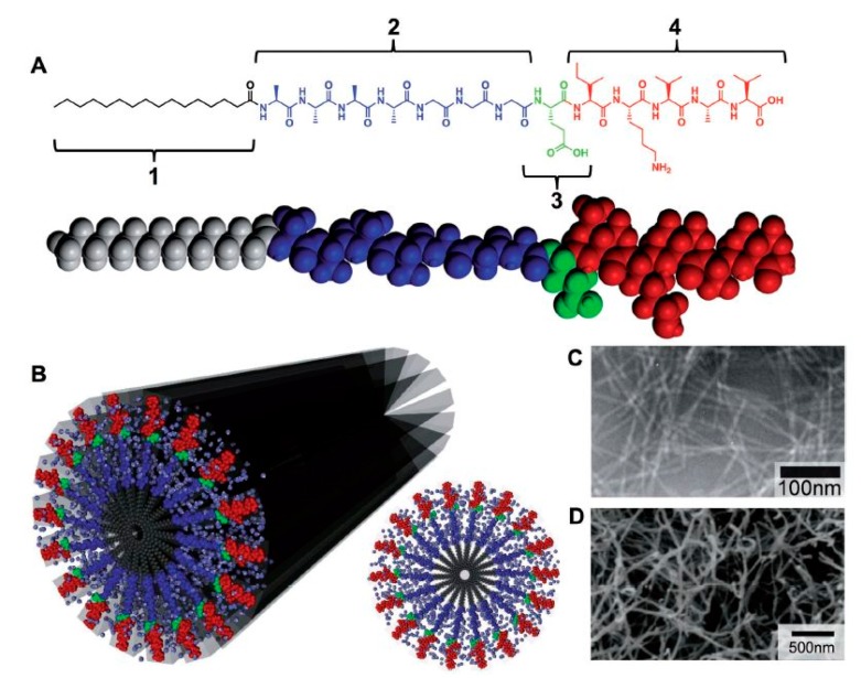
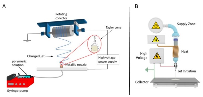
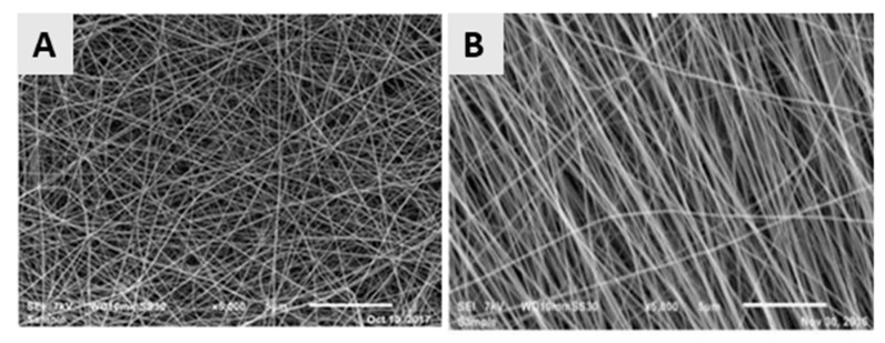
This paper provides a comprehensive overview of nanofibrous structures for tissue engineering purposes and the role of non-thermal plasma technology (NTP) within this field. Special attention is first given to nanofiber fabrication strategies, including thermally-induced phase separation, molecular self-assembly, and electrospinning, highlighting their strengths, weaknesses, and potentials. The review then continues to discuss the biodegradable polyesters typically employed for nanofiber fabrication, while the primary focus lies on their applicability and limitations. From thereon, the reader is introduced to the concept of NTP and its application in plasma-assisted surface modification of nanofibrous scaffolds. The final part of the review discusses the available literature on NTP-modified nanofibers looking at the impact of plasma activation and polymerization treatments on nanofiber wettability, surface chemistry, cell adhesion/proliferation and protein grafting. As such, this review provides a complete introduction into NTP-modified nanofibers, while aiming to address the current unexplored potentials left within the field.

Keywords: electrospun nanofibers; non-thermal plasma treatment; tissue engineering.


Conflict of interest statement

The authors declare no conflict of interest.

Figures

Figure 1
Figure 1
Schematic of the scaffold-based tissue engineering approach.
Figure 2
Figure 2
Distribution of publications published worldwide in the period 1994–2019 according to the most common used nanofibrous tissue engineering (TE) scaffold fabrication technique.
Figure 3
Figure 3
Illustration of thermally-induced phase separation (TIPS) production steps.
Figure 4
Figure 4
Scanning electron microscopy (SEM) micrograph of poly-l-lactic acid (PLLA) nanofibrous meshes prepared from a 5 w/v% PLLA/tetrahydrofuran (THF) solution at 8 °C—reproduced. Reproduced with permission from [62], Copyright Wiley, 1999.
Figure 5
Figure 5
SEM images of PLLA nanofibers and microspheres obtained from PLLA/dimethylformamide (DMF) solutions as a function of PLLA concentration: (A) 1 w/v%, (B) 3 w/v%, (C) 5 w/v% and (D) 7 w/v% (quenching time: 10 min; crystallization temperature: −10 °C; scale bar: 10 µm)—reproduced with permission from [65], Copyright Royal Sociaty of chemistry, 2015.
Figure 6
Figure 6
(A) Molecular structure of a peptide-amphiphile (PA) with four rationally designed chemical entities. (B) Molecular graphic illustration of the PA molecule and its self-assembly into nanofibers in addition to a schematic of the cross-section of these fibers (C) TEM images of isolucinelysine-valine-alanine-valine (IKVAV) nanofibers and (D) SEM micrograph of an IKVAV nanofiber mesh—reproduced with permission from [82]. Copyright Wiley, 2013.
Figure 7
Figure 7
A schematic representation of (A) a polymer solution reproduced with permission from [106]. American chemical society, 2018 and (B) polymer melt electrospinning system—reproduced with permission from [107]. Copyright Elsevier, 2016.
Figure 8
Figure 8
SEM images of the poly-ε-caprolactone (PCL) (A) Random nanofibers; collector speed: 300 rpm—Reproduced with permission from [106]. American Chemical society, 2018 and (B) aligned nanofibers; collector speed: 3000 rpm (for both images: concentration = 14%, mixture of formic and acetic acid (9:1), voltage: 32–33 kV)—reproduced with permission from [119]. Copyright Elseivier, 2018.
Figure 9
Figure 9
Schematic representation of an electrospinning set-up used for coaxial electrospinning—reproduced with permission from [131]. Copyright American Chemical Society, 2004.
Figure 10
Figure 10
SEM images of the electrospun poly(lactic-co-glycolic acid) (PLGA)/PCL nerve guide conduit and (A) magnified details of the tube wall (B): microfibers and nanofibers range in diameter from approximately 280 nm to 8 μm—reproduced with permission from [138]. Copyright BMC biotechnology, 2008.
Figure 11
Figure 11
Chemical structure of the most commonly used synthetic polymers for the fabrication of electrospun TE scaffolds.
Figure 12
Figure 12
Scanning electron micrographs of control-group electrospun PGA at 1600× magnification. (A): 67 mg/mL with 0.22 ± 0.07-µm fibers (excluding beads) and 1.84 ± 1.08-µm2 pores. (B): 100 mg/mL with 0.42 ± 0.17-µm fibers and 3.53 ± 2.78-µm2 pores. (C): 143 mg/mL with 0.88 ± 0.37-µm fibers and 13.22 ± 7.45-µm2 pores—reproduced with permission from [155]. Copyright Wiley, 2004.
Figure 13
Figure 13
Typical plasma reactor set-ups of (A) a dielectric barrier discharges (DBD), (B) a capacitively coupled plasma (CCP) and (C) an inductively coupled plasma (ICP) with helical coil configuration and (D) an ICP with planar coil configuration—reproduced with permission from [230]. Copyright Springer, 2017.
Figure 14
Figure 14
Fluorescent images one day (top) and seven days (bottom) post-seeding of human foreskin fibroblasts (HFF) cells after culturing on untreated and Ar plasma-modified PCL nanofibrous meshes—reproduced with permission from [106]. Copyright American Chemical Society, 2018.
Figure 15
Figure 15
Schematic diagram of porcine mesenchymal stem cells (pMSCs) adhesion on pristine PLLA nanofibrous scaffolds (PLLA NFS) and O2 plasma-treated PLLA nanofibrous scaffolds (P-PLLA NFS)—reproduced with permission from [246]. Copyright Elsevier, 2014.
Figure 16
Figure 16
Cross-sectional images of (A) untreated and (B) Ar plasma-modified scaffolds sustained after in vitro study with BAECs in the serum medium for five days. Top and bottom scaffold surfaces are marked by dashed lines—reproduced with permission from [248]. Copyright Liebert, 2013.
Figure 17
Figure 17
SEM micrographs of nHAC-kn cultured for seven days onto untreated (A) and Ar plasma-modified (B) 3D porous nanofibrous silk fibroin scaffolds—reproduced with permission from [249]. Copyright Elsevier, 2008.
Figure 18
Figure 18
Visualization of the effect of air plasma treatment on tubular PCL scaffolds after vascular implantation: plasma modification not only promoted the invasion of the cells in the scaffold wall (A,B), but also enhanced the densely cellularized area (C) and the number of capillaries in the scaffold wall (D)—reproduced with permission from [250]. Copyright Elsevier, 2013.
Figure 19
Figure 19
Growth of 3T3 fibroblasts after seeding on various PLGA nanofibers after one, three and five days (plasma exposure time not specified in the paper)—reproduced with permission from [260]. Copyright Springer, 2007.
Figure 20
Figure 20
Visualization of the proliferation of HCAECs on plasma-modified tubular nanofibrous P(LLA-CL) conduits 10 days after cell culturing: (A,B) SEM micrographs of the cell-seeded scaffolds: (A) cross-section of the scaffold, (B) higher magnification image of the quadrangle shown in (A); (C) cross-section of the scaffold after H&E staining and (D) cross-section of the scaffold after immunostaining of PECAM-1. Original magnification: (A) 80×, (B) 2000×, (C) 200× and (D) 630×. Scale bar: (A) 500 µm, (B,C) 2 mm and (D) 100 µm—reproduced with permission from [135]. Copyright Wiley, 2009.
Figure 21
Figure 21
Proliferation of Schwann cells seeded on TCPS, electrospun silk fibroin (SF)/ polyethylene oxide (PEO) nanofibrous scaffolds and electrospun laminin (LN)-functionalized SF/PEO nanofibrous scaffolds at day 1, 3 and 5 (p < 0.01 (**), p < 0.005 (***) and p < 0.0001 (****)—reproduced with permission from [270]. Copyright Wiley, 2018.
Figure 22
Figure 22
Grafting performance of heparin to silk fibroin scaffolds as a function of Ar plasma treatment time (* p < 0.05, significant different between the grafting efficiency of plasma-treated scaffolds and untreated scaffolds; # p < 0.05, significant different between the performance at an Ar plasma exposure time of 5 min compared to an Ar plasma exposure time of 1, 3 and 7 min)—reproduced with permission from [273]. Copyright Elsevier, 2011.
Figure 23
Figure 23
SEM images of CaCO3 enrichment on untreated, O2, NH3, and Ar plasma-treated PCL nanofibrous scaffolds at different magnifications—reproduced with permission from [244]. Copyright Royal Society of Chemistry, 2018.
Figure 24
Figure 24
Adhesion of MSCs on the surface of untreated PCL (A), COOH-coated PCL (B), COOH-coated PCL with physically adsorbed PRP (C) and COOH-coated PCL with covalently immobilized PRP (D). All images were taken with a magnification of 40× and the scale bar corresponds to 50 µm—reproduced from [294,296]. Copyright Wiley, 2007.
Figure 25
Figure 25
SEM images of PCL nanofibers before (A) and after 1-propanethiol plasma polymerization with a plasma exposure time of 5 s (B), 10 s (C), 30 s (D) and 60 s (E) (scale bars = 5 and 10 µm)—reproduced with permission from [301]. Copyright Elsevier, 2019.

References

    1. Langer R., Vacanti J.P. Tissue engineering. Science. 1993;260:920–927. doi: 10.1126/science.8493529. - DOI - PubMed
    1. Hollister S.J. Porous scaffold design for tissue engineering. Nat. Mater. 2005;4:518–524. doi: 10.1038/nmat1421. - DOI - PubMed
    1. Risbud M. Tissue engineering: Implications in the treatment of organ and tissue defects. Biogerontology. 2001;2:117–125. doi: 10.1023/A:1011585117310. - DOI - PubMed
    1. O’brien F.J. Biomaterials & scaffolds for tissue engineering. Mater. Today. 2011;14:88–95.
    1. Priya S.G., Jungvid H., Kumar A. Skin tissue engineering for tissue repair and regeneration. Tissue Eng. Part B Rev. 2008;14:105–118. doi: 10.1089/teb.2007.0318. - DOI - PubMed