Review
. 2020 Mar;32(9):e1903862.
doi: 10.1002/adma.201903862. Epub 2020 Jan 16.

High-Aspect-Ratio Nanostructured Surfaces as Biological Metamaterials

Affiliations
Review

High-Aspect-Ratio Nanostructured Surfaces as Biological Metamaterials

Stuart G Higgins et al. Adv Mater. 2020 Mar.

Abstract

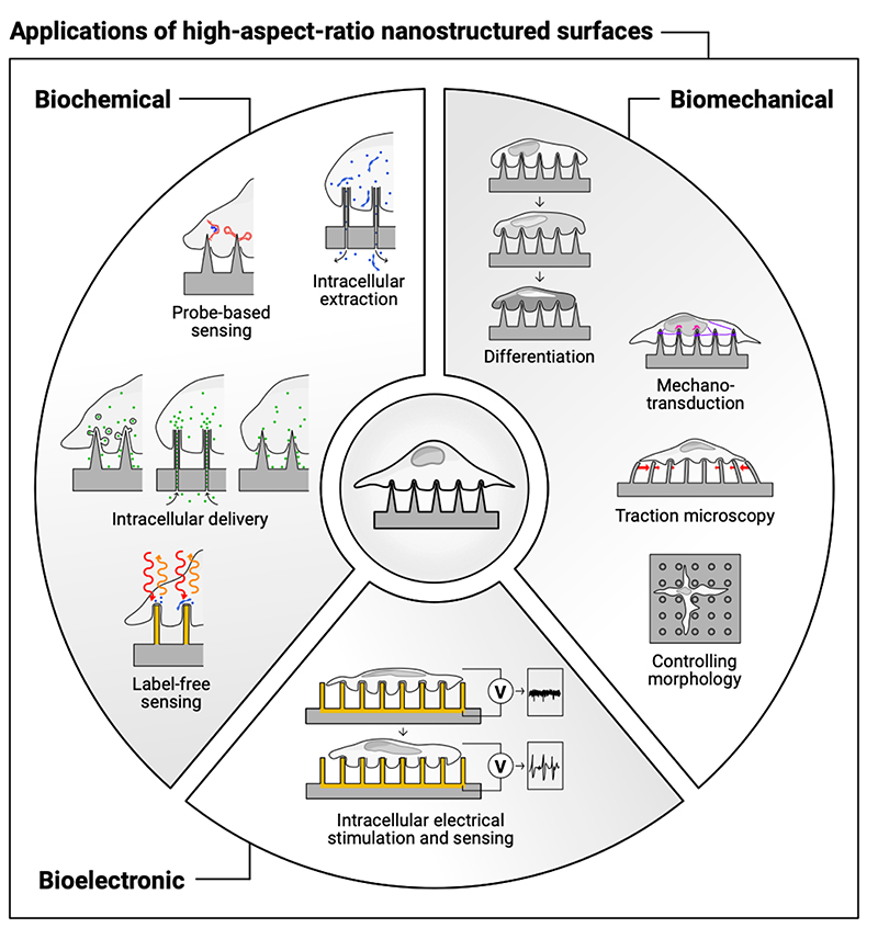
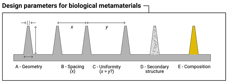
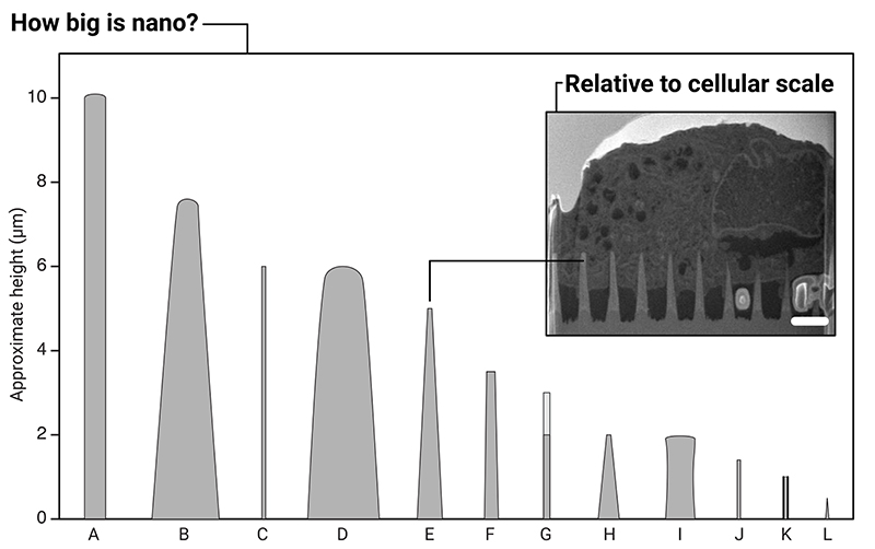
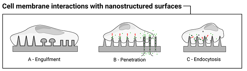
Materials patterned with high-aspect-ratio nanostructures have features on similar length scales to cellular components. These surfaces are an extreme topography on the cellular level and have become useful tools for perturbing and sensing the cellular environment. Motivation comes from the ability of high-aspect-ratio nanostructures to deliver cargoes into cells and tissues, access the intracellular environment, and control cell behavior. These structures directly perturb cells' ability to sense and respond to external forces, influencing cell fate, and enabling new mechanistic studies. Through careful design of their nanoscale structure, these systems act as biological metamaterials, eliciting unusual biological responses. While predominantly used to interface eukaryotic cells, there is growing interest in nonanimal and prokaryotic cell interfacing. Both experimental and theoretical studies have attempted to develop a mechanistic understanding for the observed behaviors, predominantly focusing on the cell-nanostructure interface. This review considers how high-aspect-ratio nanostructured surfaces are used to both stimulate and sense biological systems.

Keywords: biological metamaterials; high-aspect-ratio nanostructures; nanoneedles; nanopillars; nanowires.


Conflict of interest statement

Conflict of Interest

The authors declare no conflict of interest.

Figures

Figure 1
Figure 1. High-aspect-ratio nanostructured surfaces are used to stimulate and sense the biochemical, biomechanical, and bioelectronic environment of cells.
Figure 2
Figure 2
Design parameters to consider for high-aspect-ratio nanostructured surfaces that act as biological metamaterials. These are: (A) geometry, including the height, tip-width and base-width of the nanostructure; (B) the spacing between nanostructures; (C) the uniformity of the spacing of the nanostructures (are the nanostructures spaced with a regular periodicity, or stochastically?); (D) the presence of any secondary structure, for example the use of porous materials; (E) the underlying bulk material (e.g. silicon, gold, polymer, etc).
Figure 3
Figure 3
Illustration of the relative sizes of a selection of high-aspect-ratio nanostructures used in biointerfacing studies. A: ordered silicon pillar arrays for cell transfection.[22] B: diamond nanoneedle array for delivering probes and anti-cancer drugs into cells.[23] C: silicon nanowires for gene delivery.[24] D: plasmonic micropillars for cell traction force measurements.[25] E: porous silicon nanoneedles for in vivo growth factor delivery into muscle tissue.[26] F: silicon nanowire arrays for cell transfection.[27] G: vertical nanowire electrode arrays for interfacing neuronal cells.[28] H: diamond nanoneedle arrays for intracellular delivery.[29] I: silicon micropillar arrays for investigating single and collective cell behaviors on structured surfaces.[30] J: vertical nanopillars for studying nuclear deformation.[31] K: hollow nanostraws for intracellular sampling and longitudinal monitoring.[32] L: vertical carbon nanofibre electrodes for electrochemical intracellular communication.[33] (Note: here we use the authors’ original nomenclature for each description, to reflect the variety of terms found within the literature. In some reports, multiple geometries were fabricated, here a representative geometry is shown.) Inset: micrograph of FIB-SEM milled cross-section of a human mesenchymal stem cell interfacing porous silicon nanoneedles, scale bar 2 μm, adapted under the terms of CC BY license.[34] Copyright 2019, The Authors.
Figure 4
Figure 4
Illustration of the different ways the cell membrane can interact with high-aspect-ratio nanostructures. The cell membrane can engulf nanostructures to varying degrees (A), penetration of the membrane can occur under specific conditions (B), and there is evidence nanostructured surfaces can directly stimulate endocytosis (C). Note: these scenarios are not mutually exclusive.
Figure 5
Figure 5
Illustration of a range of different methods used to interface high-aspect-ratio nanostructured surfaces with cells, see the main text for corresponding references. The methods include: (A) seeding the cells and allowing them to settle under gravity onto the substrate; (B) either manually or mechanically interfacing the surface from above; (C) sandwiching the nanostructured surface with cells and centrifuging; (D) inkjet printing of cells (algae) directly onto the surface; (E) forcibly and repeatedly pipetting cells onto the surface; and (F) using a micropipette to manually push single cells onto inclined nanostructure. Once on the surface a range of poration methods can be combined to further modify the interfacing behavior, including: (G) electroporation; (H) optoporation; and (I) chemical poration techniques.
Figure 6
Figure 6
Examples of cell membranes engulfing nanostructured surfaces. (A) Nanopillar engulfment by a neuronal cell body, imaged by focused-ion-beam scanning-electron microscopy. Reproduced with permission.[82] Copyright 2017, American Chemical Society. (B) Scanning-electron-microscopy micrograph of gold mushroom-shaped electrode, plus (C) engulfment of electrode by a neuroendocrine cell (PC12). Reproduced under terms of CC BY license.[83] Copyright 2018, Spira, Shmoel, Huang and Erez. (D) Fluorescence confocal image of a human embryonic kidney (HEK293) cell cultured on an indium arsenide nanowire array (cell body green and membrane red), showing wrapping of the membrane around each nanowire (scale bar 10 μm). Reproduced with permission.[61] Copyright IOP Publishing Ltd, 2012.
Figure 7
Figure 7
Aalipour et al.’s illustration of nanostraw – cell membrane interfacing behavior. (A – C) In the absence of chemical poration the majority of nanostraws do not penetrate the membrane, (B) a few penetrate the membrane but not the actin meshwork, (C) a few penetrate both the membrane and meshwork. (D – F) Using dimethyl sulfoxide (DMSO) and latrunculin A, the cell membrane and/or actin meshwork can be chemically porated facilitating access. Scenario F provides the greatest degree of intracellular access. Reproduced with permission.[58] Copyright American Chemical Society, 2014.
Figure 8
Figure 8
Figure adapted from the work of Zhao et al., illustrating the principles of their experimental setup. (A) Scanning-electron-microscopy micrographs of their array of low-aspect-ratio nanopillars, with varying diameters (top row micrograph scale bar 10 μm, bottom row micrographs scale bars 400 nm). (B) They then seeded genome-edited cells (SK-MEL-2) onto these structures, which expressed red-fluorescent-protein-tagged clathrin (CLTA-RFP) and green-fluorescent-protein-tagged dynamin2 (DNM2-GFP). Using immunofluorescence microscopy they averaged multiple cells over multiple geometries to determine differences in intensity. (C) From this analysis they determined that nanopillar radii less than 200 nm resulted in a rapid increase in the quantity of observed proteins. Adapted with permission.[106] Copyright 2017, Springer Nature.
Figure 9
Figure 9
Gopal et al. nanoinjected cells with different cargoes to explore which uptake mechanisms were stimulated by interfacing with porous silicon nanoneedles. (A) Percentage of positive cells for different mechanism-specific cargoes. Transferrin is a clathrin-mediated endocytosis cargo, cholera toxin B-subunit (CTxB) is a caveolae-specific cargo, and dextran (Dex, tested in different molecular weights) is a micropinocytosis-specific cargo. After confirming that surface area did not affect loading efficacy, they noted that all cargoes were more successfully internalized in cells on nanoneedles compared to flat silicon wafers. (B) Focused-ion-beam scanning-electron-microscopy micrograph of nanoneedle interacting with cell membrane (scale bars 100 nm), showing two different types of vesicular structure (clathrin pits and caveolae). (C) 3D reconstruction of vesicular structures on nanoneedle (red) and non-nanoneedle (blue) regions, nanoneedles shown in green. Reproduced under the terms of CC BY license.[84] Copyright 2019, The Authors.
Figure 10
Figure 10
Illustrations and model outcomes adapted from the report by Xie et al., exploring the dynamic settling behavior of cells on nanostructures. (A) Their adhesion model proposes that, under the appropriate conditions, as a cell settles onto a nanostructure, the membrane will continue to engulf the nanostructure for a short period afterwards. (B) The driving force for engulfment is the relative vertical adhesion force between the membrane and substrate. (C + D) As the remaining contact area decreases with time, so too does the net adhesive force, resulting in a time beyond which the adhesion force becomes less than the penetration force, ultimately making spontaneous penetration increasingly unlikely. (E) The relationship between various geometric, membrane and surface parameters for their adhesion model, where the orange, green and magenta regions indicate the parameter space where penetration is possible, for the corresponding nanowire heights. Adapted with permission.[59] Copyright 2015, American Chemical Society.
Figure 11
Figure 11
A free-energy model for cell settling behavior on nanostructured surfaces, as proposed by Buch-Månson et al. (A) Scanning-electron-microscopy micrograph of cells suspended on top of nanostructure arrays in ‘top’ state (scale bar 5 μm). (B) Scanning-electron-microscopy micrograph of cells engulfing nanostructure arrays in ‘bottom’ state (scale bar 2 μm). (C) Illustration of membrane behavior as described by the model. (D) The change in free energy for the membrane – surface interaction, as a function of nanostructure density. In this model, if the overall change in free energy is greater than zero, the system favors cell settling in the ‘top’ state, and vice versa. Depending on the substrate and cell properties, the model predicts that the transition point between states will occur at different nanostructure densities. Adapted with permission.[117] Copyright 2015, John Wiley and Sons.
Figure 12
Figure 12
A phase-diagram illustrating the output from the cell-settling model of Zhou et al. The color scale indicates the degree of adhesion depth (i.e. how far the cell sinks into the nanostructures). The black and white lines indicate the boundary for cells either being a fully-engulfed ‘bottom’ or ‘top’ state. Reproduced with permission.[118] Copyright 2018, Royal Society of Chemistry.
Figure 13
Figure 13
Dissipative particle dynamics simulation of either a hydrophilic (A) or hydrophobic (B) probe penetrating a model of a lipid bilayer, for different simulation timepoints. The degree of membrane disruption is strongly influenced by the surface chemistry of the probe. Reproduced with permission.[127] Copyright 2013, Elsevier.
Figure 14
Figure 14
A two-dimensional coarse-grain molecular dynamics simulation of a strained membrane, rupturing about two different curved edges. (A + B) Sharper edges make membrane rupture more likely for a given traction force. (C + D) Capozza et al. were able to replicate this result experimentally using two different types of nanopillar, with differing sharpness edges. (E + F) Despite being relatively short, wide nanostructures, greater delivery of a membrane-impermeable dye was seen on the sharper-edged structures (compare the greater degree of red staining shown in the fluorescence micrograph E compared to F). Adapted with permission.[63] Copyright 2018, American Chemical Society.
Figure 15
Figure 15
Multiple fabrication approaches exist for fabricating high-aspect-ratio nanostructures. Patterns can be well-ordered, defined by parallel or serial patterning processes, or stochastically defined by semi-random deposition processes. Subtractive (also called top-down) processes remove material from the substrate, additive (also known as bottom-up) processes deposit material. Once fabricated, a number of techniques exist to replicate and transfer these structures into new materials and substrates.
Figure 16
Figure 16. Scanning-electron-microscopy micrographs illustrating some of the hollow nanoneedle array geometries fabricated by Nagai et al. using i-line stepper lithography. Reproduced with permission.[134] Copyright 2019, Elsevier.
Figure 17
Figure 17
Illustration of different approaches that have been used to modify the surface-chemistry of high-aspect-ratio nanostructures. Note: surface chemistry mechanisms are often complex and multiple bindings may coexist on the same surface, for example only one mechanism is shown for silane binding in C, but more are possible.[285] Similarly the mechanism of the sulfur-gold bond in D has been of considerable discussion in the literature.[286,287] In F, the blue and bold portions of the line represent the presence of an integrin-recognized peptide-binding sequence within the overall peptide.
Figure 18
Figure 18
Illustration of the approach used by Amin et al., combining high-aspect-ratio nanostructures with a poly-DL-ornithine coating, to engineer the adhesion and alignment of primary hippocampal neurons on surfaces. Reproduced under the terms of CC BY License.[299] Copyright 2019, The Authors.
Figure 19
Figure 19
Porous silicon nanoneedles used to nanoinject a growth-factor-encoding plasmid into mouse tissue. (A) intravital bright-field (top row, scale bar 100 μm) and confocal micrographs (bottom row, scale bar 50 μm), showing untreated (left), direct injected (center), and nanoinjected (right) human vascular endothelial growth factor-165 (hVEGF-165). The confocal images show the fluorescent signal from systemically injected fluorescently-tagged dextran, showing a greater degree of neovascularization in the nanoinjected tissue compared to the direct injection. (B + C) quantification of this behavior, both in terms of area of the fluorescent signal and number of nodes observed for different timepoints, averaged over multiple repeats. Adapted with permission.[26] Copyright 2015, Springer Nature.
Figure 20
Figure 20
Kim et al.’s flexible nanoneedle patch. A: Inverted silicon nanoneedles can be embedded into an elastomer, before a controlled cracking process is used to remove them from the surface. B: Photograph of fabricated patch (scale bar 1.5 cm). C: Scanning-electron-microscopy micrograph of embedded silicon nanoneedles, scale bar 20 μm (inset scale bar 600 nm). D: Confocal laser scanning micrograph, scale bar 30 μm. Reproduced under terms of CC BY-ND license.[133] Copyright 2018, The Authors.
Figure 21
Figure 21
Scanning-electron-microscopy micrograph of a microalgae cell (Chlamydomonas reinhardtii) impaled on a hollow, tapered microtube, facilitating quantum dot delivery. Reproduced with permission.[79] Copyright 2016, American Chemical Society.
Figure 22
Figure 22
Illustration of the single-particle intracellular delivery system proposed by Huang et al. A three-electrode system is used to both electroporate the cell surface, while providing electrophoretic control over the flow of charged gold nanorods. Raman Correlation Spectroscopy was used to track surface-enhanced Raman scattering from single gold nanorods passing through the nanostraws. Reproduced with permission.[360] Copyright 2019, American Chemical Society.
Figure 23
Figure 23
Electrogenic cells are often electroporated in order to allow intracellular potentials to be sensed, however Dipalo et al. have shown plasmonic nanoelectrode-based optoporation also works. (A) Recorded voltage as a function of measurement time, for a cardiac cell seeded on nanoelectrodes, showing two sequential improvements in the signal-to-noise ratio after an increasing number of electrodes are optoporated. (B) The equivalent circuit diagram model of the cell-nanostructure interface, illustrating how sequentially optoporating nanoelectrodes reduces the junction resistance between cell and electrode, while increasing the membrane seal resistance. Adapted with permission.[96] Copyright 2017, American Chemical Society.
Figure 24
Figure 24
Scanning-electron-microscopy micrographs of unpatterned (A) (scale bar 10 μm) and patterned (C) (scale bar 100 μm) arrays of silicon nanocolumns. The grid pattern provides additional guidance for neurite growth. (B) immunofluorescent micrograph showing neurons on unpatterened nanocolumns after one day in vitro, scale bar 100 μm (inset shows undifferentiated neuron on flat silicon, scale bar 20 μm). (D) Corresponding micrograph for neurons cultured on patterned silicon nanocolumn arrays after seven days in vitro, scale bar 100 μm. Adapted with permission.[154] Copyright 2017, Springer Nature.
Figure 25
Figure 25
Illustration from Hansel, Crowder et al., proposing the mechanism for cytoskeletal tension coupling between cellular microenvironment and the nuclear membrane for flat (A) and silicon nanoneedle (B) substrates. Cells on flat surfaces can readily form focal adhesions on strong cytoskeletal tension, activating Yes-associated protein (YAP). Nanoneedles disrupts focal adhesion formation, inhibiting cytoskeletal tension, reducing YAP activity. Simultaneously, direct perturbation of the nucleus results in the formation of lamin protein caps, and a physical decoupling of the two main types of lamin protein in the nucleus. Adapted under the terms of CC BY license.[34] Copyright 2019, The Authors.
Figure 26
Figure 26
Illustration from Lin et al. showing the general differentiation fates for human mesenchymal stem cells seeded on silicon nanowires with differing geometries and spring-constants. Group I: ~9 μm-high nanowires, group IV: ~26 μm-high nanowires. Note: geometry and density are convoluted, see the underlying paper for full parameters. Reproduced under the terms of CC BY license.[168] Copyright 2018, The Authors.
Figure 27
Figure 27
Paulitschke et al. used thin-base, gallium arsenide nanowires to measure the traction forces generated by amoeba (Dictyostelium discoideum). (A) false-colored scanning-electron-microscopy micrograph of a cell interacting with a nanowire. (B) fluorescent micrographs illustrating a top-down view of cells (green) deflecting nanowires (blue), with the degree of deflection indicated by the arrows. (C) individual nanowire deflection as a function of time, with corresponding calculated force (where possible to estimate), illustrating the ability to monitor dynamic changes in force. Adapted with permission.[138] Copyright 2019, American Chemical Society.
Figure 28
Figure 28
Bacterial cells (Shewanella oneidensis MR-1) show preferential attachment to silicon nanowire arrays. Cells more frequently aligning parallel to the nanowire (A and B), rather than attaching elsewhere (C and D). A and C: fluorescence micrographs, B and D: scanning-electron-microscopy micrographs, scale bars 500 μm. Adapted with permission.[470] Copyright 2013, American Chemical Society.
Figure 29
Figure 29
Fluorescent micrographs of a coculture of endothelial (LE2) and fibroblast (hTERT-BJ1) cells seeded on a continuously varying nanopillar array (low-aspect-ratio, maximum height is 250 nm). Both cells are stained red for phalloidin, endothelial cells are also stained green. Cells were segmented using image-based cell profiling and used to quantitatively determine the optimal height favoring endothelial over fibroblast cells, illustrating the benefit of both systematic geometry studies and image-based cell profiling. Adapted with permission.[272] Copyright 2013, American Chemical Society.

References

    1. Chiappini C. ACS Sens. 2017;2:1086. - PubMed
    1. Prinz CN. J Phys Condens Matter. 2015;27:233103. - PubMed
    1. Parameswaran R, Tian B. Acc Chem Res. 2018;51:1014. - PMC - PubMed
    1. McGuire AF, Santoro F, Cui B. Annu Rev Anal Chem. 2018;11:101. - PMC - PubMed
    1. Lard M, Linke H, Prinz CN. Nanotechnology. 2019;30:214003. - PubMed

LinkOut - more resources