. 2017 Nov 13;25(23):28489-28500.
doi: 10.1364/OE.25.028489. Epub 2017 Nov 2.

Simultaneous two-color imaging in digital holographic microscopy

Affiliations

Simultaneous two-color imaging in digital holographic microscopy

Nicola E Farthing et al. Opt Express. .

Abstract

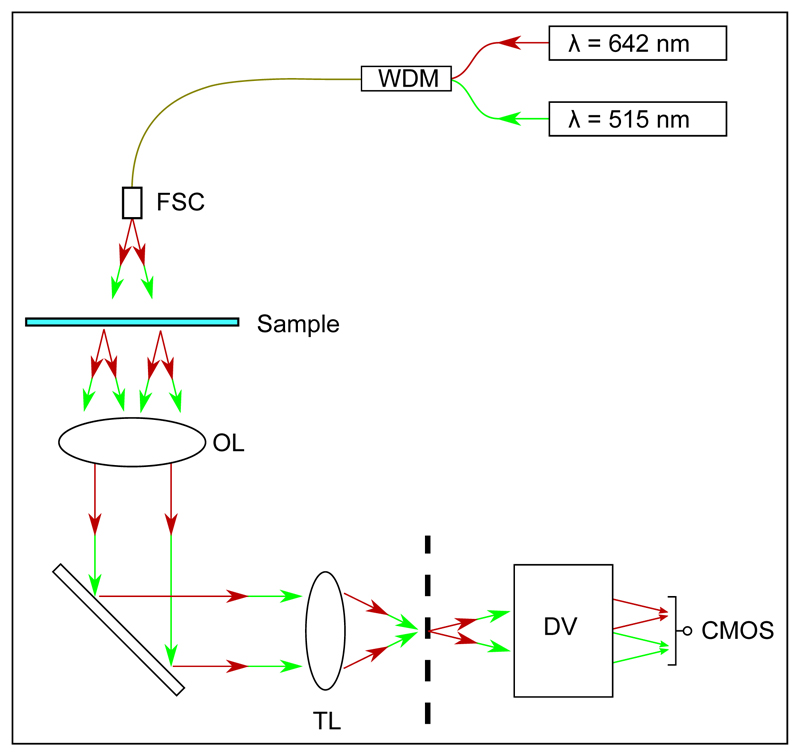
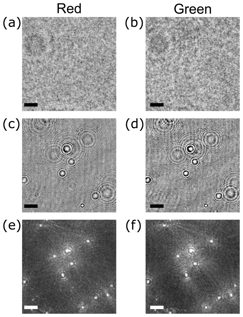
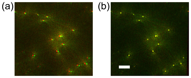
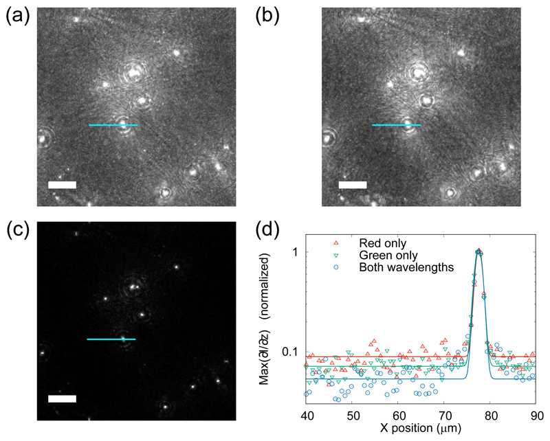
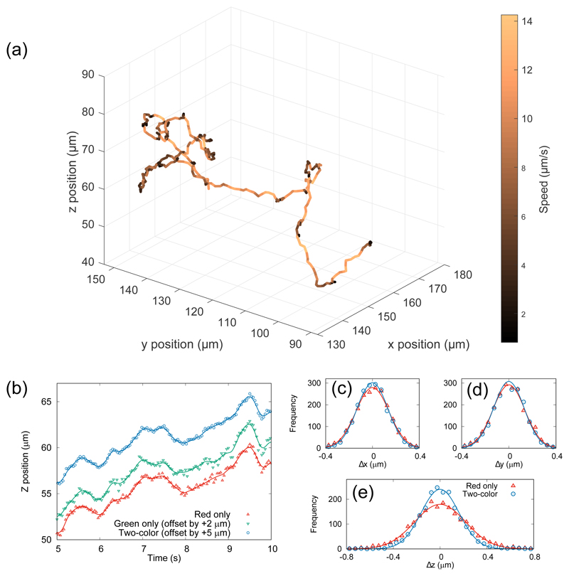
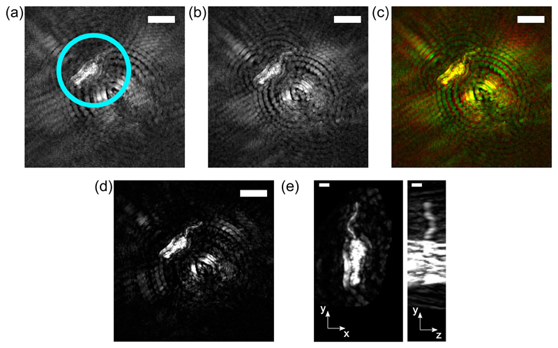
We demonstrate the use of two-color digital holographic microscopy (DHM) for imaging microbiological subjects. The use of two wavelengths significantly reduces artifacts present in the reconstructed data, allowing us to image weakly-scattering objects in close proximity to strongly-scattering objects. We demonstrate this by reconstructing the shape of the flagellum of a unicellular eukaryotic parasite Leishmania mexicana in close proximity to a more strongly-scattering cell body. Our approach also yields a reduction of approximately one third in the axial position uncertainty when tracking the motion of swimming cells at low magnification, which we demonstrate with a sample of Escherichia coli bacteria mixed with polystyrene beads. The two-wavelength system that we describe introduces minimal additional complexity into the optical system, and provides significant benefits.


Conflict of interest statement

Disclosures The authors declare that there are no conflicts of interest related to this article.

Figures

Fig. 1
Fig. 1
Optical layout for our simplified dual wavelength setup. A wavelength division multiplexer (WDM) is used to couple the two illumination wavelengths into a single fiber, which is directed onto a free-space coupler (FSC). An objective lens (OL) and tube lens (TL) produce an image of the sample at the microscope image plane, indicated as a vertical dashed line. The DualView apparatus (DV) images this plane with unit magnification onto a CMOS camera, spatially separating images created by the two illumination sources (see text).
Fig. 2
Fig. 2
Example two-color holographic images of a mixture of E. coli cells and polystyrene beads (see text), showing intermediate processing steps. Panels (a) and (b) show raw holographic data. The images in panels (c) and (d) show the same data, but with the static background removed (see text). The bottom row shows the maximum intensity projection of the intensity gradient stacks Igrad (x, y, z; t); this data can be used either for image registration or for object localization. The scale bars represent 25 μm in all panels.
Fig. 3
Fig. 3
Combining images of a mixture of E. coli cells and polystyrene beads (see text). (a) A superposition of images from red and green channels. The green image is shifted to the right, and suffers a slight stretching in the same direction. (b) A superposition of the red channel with the transformed green channel. The scale bar in panel (b) represents 30 μm. The scale in panel (a) is approximately the same, although red and green channels differ in scale by approximately 1.5% (see text).
Fig. 4
Fig. 4
Signal-to-noise ratio improvements using two-color DHM on a mixture of E. coli cells and polystyrene beads. Panels (a) and (b) show maximum intensity projections of gradient stacks from the red and green channels, respectively. Panel (c) shows the effect of multiplying the channels together. Panels (a–c) are displayed using a linear mapping from black for the minimum value, to white for the maximum value. Panel (d) shows a line profile along the path indicated with a light blue line in panels (a–c). The data in panel (d) have been scaled to have a maximum of 1, and fitted with a Gaussian curve (see text), to demonstrate improvements in the SNR. The scale bars in panels (a–c) represent 25 μm.
Fig. 5
Fig. 5
(a) A three-dimensional reconstruction of the swimming trajectory of bacterial cell, color-coded with instantaneous swimming speed. The total track duration is 40 seconds. (b) Five seconds of data showing the z-position as a function of time from the red channel only (bottom), the green channel only (middle, offset by 2 μm) and using both channels combined (top, offset by 5 μm). The black lines through the data points show the spline-smoothed track used to characterize the localization noise (see text). (c–e) Histograms of residuals when a spline fit is removed from the three-dimensional trajectory shown in (a). The one- and two-color systems achieve similar accuracy in the plane normal to the optical axis (Δx and Δy), but the two-color method reduces uncertainty in the axial coordinate (Δz), shown by the narrower histogram in panel (e).
Fig. 6
Fig. 6
Example data acquired from a subject with heterogeneous scattering properties: a promastigote L. mexicana cell. (a) and (b) show the red and green maximum intensity projection images, respectively (scale bar = 10 μm in each). Panel (c) shows a color image with the red and green channels combined, so that the artifacts can be seen to lie in different positions in each channel. Panel (d) shows the maximum intensity projection of the registered ‘joint’ image (scale bar = 10 μm), and panel (e) shows two orthogonal projections of the cell, demonstrating the three-dimensional reconstruction of the flagellum, the hair-like projection at the top of the cell (scale bar = 2 μm).

References

    1. Goodman J, Lawrence RW. Digital image formation from electronically detected holograms. Appl Phys Lett. 1967;11:77–79.
    1. Schnars U, Jüptner W. Direct recording of holograms by a ccd target and numerical reconstruction. Appl Opt. 1994;33:179–181. - PubMed
    1. Haddad WS, Cullen D, Solem JC, Longworth JW, McPherson A, Boyer K, Rhodes CK. Fourier-transform holographic microscope. Appl Opt. 1992;31:4973–4978. - PubMed
    1. Kim M. Principles and techniques of digital holographic microscopy. SPIE Rev. 2010;1 018005.
    1. Xu W, Jericho MH, Meinertzhagen IA, Kreuzer HJ. Digital in-line holography for biological applications. Proc Natl Acad Sci. 2001;98:11301–11305. - PMC - PubMed

LinkOut - more resources