. 2020 Jan 21;10(1):782.
doi: 10.1038/s41598-020-57485-x.

Toward Reservoir-on-a-Chip: Rapid Performance Evaluation of Enhanced Oil Recovery Surfactants for Carbonate Reservoirs Using a Calcite-Coated Micromodel

Affiliations

Toward Reservoir-on-a-Chip: Rapid Performance Evaluation of Enhanced Oil Recovery Surfactants for Carbonate Reservoirs Using a Calcite-Coated Micromodel

Wonjin Yun et al. Sci Rep. .

Abstract

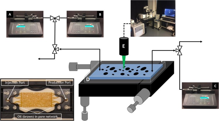
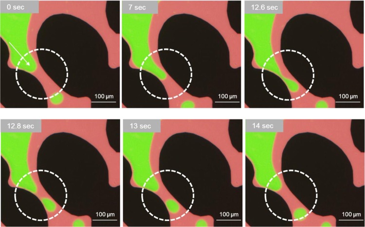
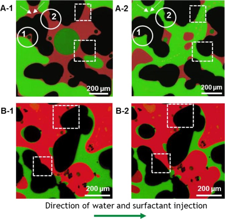
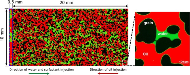
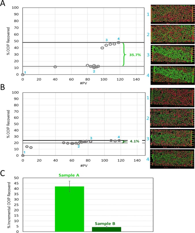
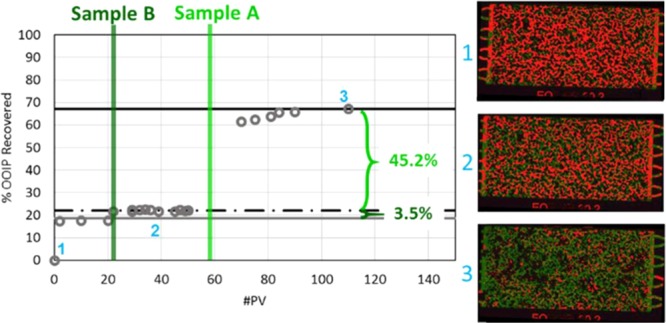
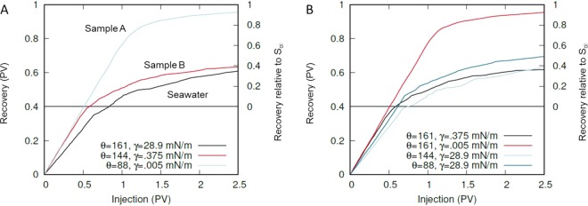
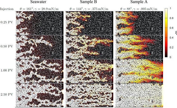
Enhanced oil recovery (EOR) plays a significant role in improving oil production. Tertiary EOR, including surfactant flooding, can potentially mobilize residual oil after water flooding. Prior to the field deployment, the surfactant performance must be evaluated using site-specific crude oil at reservoir conditions. Core flood experiments are common practice to evaluate surfactants for oil displacement efficiency using core samples. Core flood experiments, however, are expensive and time-consuming and do not allow for pore scale observations of fluid-fluid interactions. This work introduces the framework to evaluate the performance of EOR surfactants via a Reservoir-on-a-Chip approach, which uses microfluidic devices to mimic the oil reservoir. A unique feature of this study is the use of chemically modified micromodels such that the pore surfaces are representative of carbonate reservoir rock. To represent calcium carbonate reservoir pores, the inner channels of glass microfluidic devices were coated with thin layers of calcium carbonate nanocrystals and the surface was modified to exhibit oil-wet conditions through a crude oil aging process. During surfactant screening, oil and water phases were imaged by fluorescence microscopy to reveal the micro to macro scale mechanisms controlling surfactant-assisted oil recovery. The role of the interfacial tension (IFT) and wettability in the microfluidic device was simulated using a phase-field model and compared to laboratory results. We demonstrated the effect of low IFT at the oil-water interface and wettability alteration on surfactant-enhanced oil displacement efficiency; thus providing a time-efficient and low-cost strategy for quantitative and qualitative assessment. In addition, this framework is an effective method for pre-screening EOR surfactants for use in carbonate reservoirs prior to further core and field scale testing.


Conflict of interest statement

The authors declare no competing interests.

Figures

Figure 1
Figure 1
Experimental setup showing the seawater (A), surfactant (B), and crude oil (C) injection pumps and the micromodel (D). Images were obtained via Zeiss Observer Z1 inverted microscope (E). Inset: an image of the micromodel (D) indemnifying the injection and production ports and the pore network filled with crude oil.
Figure 2
Figure 2
Pore level observation showing a thin layer of oil (red) remaining on the pore walls, preventing water (non-wetting phase) from contacting the rock surface. Snap-off events at the single-constricted pore channel (dashed-circles) throughout the oil-phase injection. (0 sec to 7 sec): non-wetting phase (water in green) penetrates as capillary pressure exceeds the capillary entry pressure. (12.6 sec to 12.8 sec): water-front enters the wider pore body in the downstream of the throat. Reduced capillary pressure causes snap-off in the upstream throat. (14 sec): waterfront recedes to its initial shape.
Figure 3
Figure 3
Microscopic images of pore-scale wettability alteration before and after 1 PV injection of Sample A and Sample B (defending fluid: red) and water phase (invading fluid: green). (A-1 and B-1): pores exhibit partially oil-wet conditions with surface affinity (dashed square) to the oil phase before Sample injection. (A-1A-2): Sample A induced wettability alteration showing water in contact with grain wall (dashed-square) and cooperative pore filling (dashed arrow) of invading fluid (water). Circle 1 shows recovery of trapped residual oil by water invasion into capillary end. Circle 2 demonstrates water enters pore throat without snap-off due to the reduction of oil-wet characteristic. (B-1B-2): Sample B does not result in significant wettability alteration (dashed-square) and does not mobilize much trapped oil.
Figure 4
Figure 4
Single fluorescence image (right) of the EOR vuggy microfluidic chip and a fully stitched fluorescence image containing >500 tiles (left). The dimensions of the porous matrix are 20 mm by 10 mm with a 20 µm depth. Flow distribution channel (blue rectangle) has a width of 0.5 mm.
Figure 5
Figure 5
Cumulative oil recovery (% OOIP) plotted against cumulative pore volume (PV) injected for (A) Sample A and (B) Sample B. Incremental oil recovery after injection of 1 PV of surfactant was 35.7% for Sample A and 4.1% for Sample B. (C) Average incremental recovery from three runs of Sample A versus Sample B. Sample A recovered ~10× more oil than Sample B.
Figure 6
Figure 6
Cumulative oil recovery (%OOIP) from a consecutive injection series where 1 PV of Sample B was followed by seawater and then by 1 PV of Sample A then by seawater. Incremental oil recovery after injection of 1 PV of Sample B was 3.5% and the subsequent 1 PV injection of Sample A followed by seawater resulted in 45.2% incremental recovery.
Figure 7
Figure 7
Simulated oil recovery from the EOR microchip as a function of the pore volumes of injected water for different interfacial tensions and contact angles. The Y-axis of the plots has been rescaled to show oil recovery relative to the experimental initial condition (Soi = 60%) for easier comparison with experimental results. (A) Wettability and IFT chosen to match experiment. (B) Simulation of different combinations of IFT and contact angle reveals the significant effect of low IFT on improving oil recovery.
Figure 8
Figure 8
Snapshots of the EOR microchip simulation for interfacial tensions and contact angles corresponding to Fig. 7A. The solid pore walls are gray, and ξ is the depth-averaged volume fraction of water in the pores.

References

    1. Lifton VA. Microfluidics: an enabling screening technology for enhanced oil recovery (EOR) Lab Chip. 2016;16:1777–1796. doi: 10.1039/C6LC00318D. - DOI - PubMed
    1. Shah, D. O. Surface Phenomena in Enhanced Oil Recovery. (Springer US, 2013).
    1. Lake, L. W., Johns, R., Rossen, B. & Pope, G. Fundamentals of Enhanced Oil Recovery. (Society of Petroleum Engineers, 2014).
    1. Datta SS, Ramakrishnan TS, Weitz DA. Mobilization of a trapped non-wetting fluid from a three-dimensional porous medium. Phys. Fluids. 2014;26:022002. doi: 10.1063/1.4866641. - DOI
    1. Manrique EJ, Muci VE, Gurfinkel ME. EOR Field Experiences in Carbonate Reservoirs in the United States. SPE Reserv. Eval. Eng. 2007;10:667–686. doi: 10.2118/100063-PA. - DOI