. 2020 Feb 26;120(4):2171-2214.
doi: 10.1021/acs.chemrev.9b00399. Epub 2020 Jan 28.

Advances in Conjugated Microporous Polymers

Affiliations

Advances in Conjugated Microporous Polymers

Jet-Sing M Lee et al. Chem Rev. .

Abstract

Conjugated microporous polymers (CMPs) are a unique class of materials that combine extended π-conjugation with a permanently microporous skeleton. Since their discovery in 2007, CMPs have become established as an important subclass of porous materials. A wide range of synthetic building blocks and network-forming reactions offers an enormous variety of CMPs with different properties and structures. This has allowed CMPs to be developed for gas adsorption and separations, chemical adsorption and encapsulation, heterogeneous catalysis, photoredox catalysis, light emittance, sensing, energy storage, biological applications, and solar fuels production. Here we review the progress of CMP research since its beginnings and offer an outlook for where these materials might be headed in the future. We also compare the prospect for CMPs against the growing range of conjugated crystalline covalent organic frameworks (COFs).


Conflict of interest statement

The authors declare no competing financial interest.

Figures

Figure 1
Figure 1
Types of porous organic polymer frameworks and their coupling chemistries. Porous polymers from left to right: covalent organic frameworks (COFs), hypercrosslinked polymers (HCPs), covalent triazine frameworks (CTFs), porous aromatic frameworks (PAFs), and conjugated microporous polymers (CMPs). Note that these classifications can overlap somewhat; for example, some COFs are also conjugated, and not all COFs reported are particularly crystalline.
Figure 2
Figure 2
Annual publications on CMPs and related materials since their discovery (assessed 4th January 2019). “CMP papers” (black) were found by searching for CMP-specific papers that cite back to key classic CMP studies. Only papers that relate directly to CMP research are included; that is, no papers that give general background references in introduction sections, etc. Searched terms are from the title search with Web of Science, Thomson Reuters database. The full list of “CMP papers” (464 papers in total) can be found in the Supporting Information, including papers that are not referred directly in this review.
Figure 3
Figure 3
A timeline for the development of CMPs and related materials. From top left: 2007, first reported CMP, CMP-1; 2008, homocoupled CMP, HCMP-1; photoluminescence, P1; 2009, first reported PAF, PAF-1; 2010, light harvesting, PP-CMP; catalysis, FeP-CMP; 2011, band gap tuning, YPy; metal–organic CMPs, MO-CMPs; supercapacitors, aza-CMP; 2012, soluble CMPs, SCMPs; sensing devices, TCB-CMP; CTF-type polymers, P1; 2013, core–shell CMPs, TPES-PPC-CMPs; 2014, conjugated PIMs, C-PIMs; lithium-ion batteries, HATN-CMP; 2015, photocatalytic H2 evolution; CP-CMPs; 2017, a report suggests overall water splitting in CMPs, 2D conjugated COF/2D CMP; 2018, CMP membrane, and 2019, tunable surface area and porosity.
Figure 4
Figure 4
Reaction schemes for the synthesis of CMPs. (a) Sonogashira-Hagihara, (b) Suzuki-Miyaura, (c) Yamamoto, (d) Heck, (e) cyclotrimerization, (f) phenazine ring fusion, (g) Schiff-base, (h) heterocycle linkages, (i) alkyne metathesis, (j) oxidative coupling, (k) Buchwald-Hartwig, (l) electropolymerization, and (m) hypercrosslinking linear polymers.
Figure 5
Figure 5
Unconventional CMP synthesis routes. (a) Microwave synthesis. (b) Mechanochemical synthesis. (c) Synthesis of CMPs on a substrate.
Figure 6
Figure 6
Synthesis of poly(aryleneethynylene) network, CMP-1.
Figure 7
Figure 7
Synthesis of pyrene-based CMP, Py-PP.
Figure 8
Figure 8
Synthesis of iron(III) porphyrin-based CMP, FeP-CMP.
Figure 9
Figure 9
(a) Linear sweep voltammetry curves for CoP-CMP800 at different rotation rates in O2-saturated 0.1 M KOH at 10 mV s–1. Inset shows the Koutecky–Levich (K-L) plot. (b) Linear sweep voltammetry curves for various CoP-CMP materials and Pt/C in O2-saturated 0.1 M KOH at 10 mV s–1 at 1600 rpm. (c) RRDE test of the ORR on CoP-CMP800 in O2-saturated 0.1 M KOH electrolyte at 1600 rpm. Inset shows the electron transfer number (n) against electrode potential. (d) The n values of various CoP-CMPs and Pt/C against electrode potential. Reprinted with permission from ref (121). Copyright 2014 Wiley-VCH.
Figure 10
Figure 10
Synthesis of CMP photoredox catalysts using SiO2 nanoparticle templates to control porosity.
Figure 11
Figure 11
(a) Synthesis of polybenzobisthiadiazole-based CMPs series. (b) Diffuse reflectance UV–vis spectra. (c) Conduction band (CB) and valence band (VB) positions of P-BBTs. Adapted with permission from ref (130). Copyright 2016 Wiley-VCH.
Figure 12
Figure 12
(a) Synthesis of Eosin Y dye-embedded porous organic polymers (EY-POPs).
Figure 13
Figure 13
(a) Synthesis of luminescent pyrene-based CMPs. Photographs of the CMPs under irradiation with UV light (λexcit = 365 nm) in the solid state, (b) YPy, (c) YDPPy, (d) YDBPy, and (e) SDBPy. (f) Photographs of suspensions of the CMPs in THF (10 mg/10 mL). (g) Photoluminescent spectra of the monomer TBrPy and the resulting polymers measured in solid state powder (λexcit = 360 nm). Reprinted with permission from ref (44). Copyright 2011 The Royal Society of Chemistry.
Figure 14
Figure 14
Synthesis of core–shell structured CMPs. Reprinted with permission from ref (27). Copyright 2013 The Royal Society of Chemistry.
Figure 15
Figure 15
(a) Photographs of TPE-NCMPs films by blending with poly(vinyl alcohol). (b) Emission colors from CIE 1931 chromaticity diagram calculated from the fluorescence spectrum of various doping levels of PhB in TPE-NCMP films. Reprinted from ref (134). Copyright 2014 American Chemical Society.
Figure 16
Figure 16
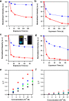
Fluorescence quenching of TCB-CMP (red) and its linear analogue (blue) at 25 °C upon exposure to vapors of (a) 2,4-dinitrotoluene, (b) 2-nitrotoluene, (c) nitrobenzene, or (d) 1,4-benzoquinone vapors. Inset in (c): luminescence images of TCB-CMP in the presence and absence of nitrobenzene under a hand-held UV lamp. Reprinted from ref (48). Copyright 2012 American Chemical Society.
Figure 17
Figure 17
(a) Synthesis of LMOPs by the Heck reaction.
Figure 18
Figure 18
Synthesis of triarylboron-linked CMP, BCMP-3.
Figure 19
Figure 19
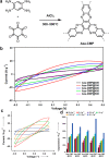
(a) Synthesis of Aza-fused CMPs by high temperature phenazine ring fusion reaction in an ampule. (b) Cyclic voltammograms of Aza-CMPs at a scan speed of 100 mV s–1. (c) Cyclic voltammogram of Aza-CMP@300 at a scan rate of 25 (blue), 50 (orange), 100 (green), and 200 mV s–1 (red), and hexaazatriphenylene (HAT) at a scan rate of 100 mV s–1 (black). (d) Capacitance of Aza-CMPs at varying current densities. Adapted with permission from ref (46). Copyright 2011 Wiley-VCH.
Figure 20
Figure 20
(a) First and (b) first to tenth cyclic voltammetry cycle of 1.5 × 10⁻⁵ Zn-mTCPP in CH2Cl2. (c) Relationship of film thickness with scan cycles. (d) Cyclic voltammogram of CMP film in monomer-free electrolyte at different scan rates. Reprinted with permission from ref (104). Copyright 2015 Wiley-VCH.
Figure 21
Figure 21
(a) Pore size distributions of CMP-1 and pyrolyzed products calculated by NL-DFT. (b) Cyclic voltammograms of N3-CMP-1 at varying scan rates between 10 and 200 mV s–1. (c) Cyclic voltammograms of N3-CMP-1 at varying scan rates between 200 and 1000 mV s–1. (d) Cycling stability of N3-CMP-1 at a current density of 5 A g–1. Adapted with permission from ref (143). Copyright 2016 The Royal Society of Chemistry.
Figure 22
Figure 22
Microwave-assisted Schiff-base condensation polymerization of KECMP-1.
Figure 23
Figure 23
(a) Synthesis of polyaminoanthraquinone networks. (b) CV curves of polyaminoanthraquinones in 0.5 M H2SO4 at a scan rate of 10 mV s–1. (c) Proposed charge/discharge mechanism of PAQTA. Reprinted with permission from ref (100). Copyright 2018 Wiley-VCH.
Figure 24
Figure 24
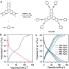
(a) Synthesis of redox-active, HATN-CMP. (b) First charge (blue) and discharge (red) profiles of HATN-CMP cell. (c) Charge–discharge profiles of HATN-cell for 50 cycles. Adapted with permission from ref (51). Copyright 2014 The Royal Society of Chemistry.
Figure 25
Figure 25
(a) Synthesis of redox-active, PDCzBT. Electrochemical performance of PDCzBT for lithium-ion batteries: (b) cyclic voltammogram profiles. (c) Charge–discharge profiles at a current density of 20 mA g–1. (d) Cycling performance at a current density of 200 mA g–1 (inset is cycle performance and Coulombic efficiency at 100 mA g–1). (e) Rate performance at current densities from 20 to 2000 mA g–1. Reprinted with permission from ref (141). Copyright 2015 The Royal Society of Chemistry.
Figure 26
Figure 26
Schematic of charging mechanisms for polythiophene (PT) and P33DT. Reprinted with permission from ref (146). Copyright 2018 Wiley-VCH.
Figure 27
Figure 27
(a) Synthesis of TPBCz-CMP films. (b) Fluorescence intensity of CMP films upon immersion in saline solutions of dopamine. (c) Recycling tests of CMP films in 10–8 M dopamine saline solution. Adapted with permission from ref (103). Copyright 2014 Wiley-VCH.
Figure 28
Figure 28
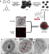
(a) Synthesis of nano-CTFs and encapsulation of DOX. Bio-TEM images of (b) HeLa cell control and (c) CTF-DOX and (d) DOX-treated HeLa cells after 6 h. Reprinted from ref (148). Copyright 2016 American Chemical Society.
Figure 29
Figure 29
(a) Synthesis scheme of antibacterial CMP nanoparticles. (b) Schematic of bacteria inactivation with the use of CMP nanoparticles. Reprinted with permission from ref (151). Copyright 2016 The Royal Society of Chemistry.
Figure 30
Figure 30
Synthesis of photothermally active CMP-1 shells using PMAA microsphere sacrificial templates. Reprinted with permission from ref (153). Copyright 2015 The Royal Society of Chemistry.
Figure 31
Figure 31
(a) Synthesis of CMP photocatalysts, CP-CMP-1 to 15. (b) Rate of H2 evolution against optical gap of polymers CP-CMP1–15 (■) and analogous linear polymers (□). Measurements relate to 100 mg catalyst in water containing 20 vol % diethylamine as an electron donor under filtered, visible irradiation (λ > 420 nm, E < 2.95 eV). Reprinted from ref (52). Copyright 2015 American Chemical Society.
Figure 32
Figure 32
Synthesis of Nx-COFs from Nx-aldehydes and hydrazine for tunable photocatalytic H2 evolution.
Figure 33
Figure 33
Structures of Mx monomers and the Suzuki-Miyaura polymerization to produce PCP photocatalysts.
Figure 34
Figure 34
(a) Structures of 1D and 3D polybenzothiadiazole CMPs. UV–vis diffuse reflectance spectra of polymers in (b) series 1 and (c) series 2. (d) HOMO and LUMO band position of polymers calculated from cyclic voltammetry (the standard error of the LUMO position is ±0.008 eV from three measurements). Adapted with permission from ref (159). Copyright 2016 Wiley-VCH.
Figure 35
Figure 35
(a) Structures of CMPs and their extended equivalent for photocatalytic H2 evolution. (b) H2 evolution rates under visible light (λ > 420 nm) correlated with the optical gap of the CMPs. Measurements were performed with 25 mg catalyst in water/MeOH/triethylamine mixture. Wavelength dependency of the photocatalytic H2 evolution for SP-CMP (insert). Reprinted with permission from ref (158). Copyright 2016 The Royal Society of Chemistry.
Figure 36
Figure 36
Synthesis of PCTF-8 photocatalyst.
Figure 37
Figure 37
(a) Synthesis of CTF library. (b) High-throughput workflow for H2 evolution testing (top row) and photographs of equipment used in the workflow (bottom row). Reprinted with permission from ref (180). Copyright 2019 American Chemical Society.
Figure 38
Figure 38
Synthesis of CTF heterostructures by sequential polymerization. Reprinted with permission from ref (182). Copyright 2019 Wiley-VCH.
Figure 39
Figure 39
(a) Structures of M0–M11, used to synthesize PCP0–PCP11. (b) Photocatalytic H2 evolution rates of PCP0–11 under full-arc irradiation for 2 h. (c) Retention ratios of H2 evolution rates of PCP0–11 under visible light and full-arc irradiation. Adapted from ref (157). Copyright 2016 American Chemical Society.
Figure 40
Figure 40
(a) Structures of PTEPB and PTEB photocatalysts. Time course of H2 and O2 production under visible light irradiation using (b) PTEPB and (c) PTEB. Reprinted with permission from ref (53). Copyright 2017 Wiley-VCH.
Figure 41
Figure 41
CMP networks (first row) with linear polymer equivalent (second row). For each pairing, the photocatalyst showing higher performance under visible light (CMP or nonporous/low porosity linear polymer) is marked with a green square. Reprinted from ref (160). Copyright 2019 American Chemical Society.

References

    1. Thommes M.; Kaneko K.; Neimark A. V.; Olivier J. P.; Rodriguez-Reinoso F.; Rouquerol J.; Sing K. S.W. Physisorption of Gases, with Special Reference to the Evaluation of Surface Area and Pore Size Distribution (IUPAC Technical Report). Pure Appl. Chem. 2015, 87, 1051.10.1515/pac-2014-1117. - DOI
    1. Kondo M.; Yoshitomi T.; Matsuzaka H.; Kitagawa S.; Seki K. Three-Dimensional Framework with Channeling Cavities for Small Molecules: {[M2(4, 4′-bpy)3(NO3)4]·XH2O}n (M = Co, Ni, Zn). Angew. Chem., Int. Ed. Engl. 1997, 36, 1725–1727. 10.1002/anie.199717251. - DOI
    1. Long J. R.; Yaghi O. M. The Pervasive Chemistry of Metal-Organic Frameworks. Chem. Soc. Rev. 2009, 38, 1213–1214. 10.1039/b903811f. - DOI - PubMed
    1. O’Keeffe M. Design of MOFs and Intellectual Content in Reticular Chemistry: A Personal View. Chem. Soc. Rev. 2009, 38, 1215–1217. 10.1039/b802802h. - DOI - PubMed
    1. Furukawa H.; Cordova K. E.; O’Keeffe M.; Yaghi O. M. The Chemistry and Applications of Metal-Organic Frameworks. Science 2013, 341, 1230444.10.1126/science.1230444. - DOI - PubMed

Publication types