. 2020 Sep 1;19(3):341-350.
doi: 10.1093/ons/opz431.

First-In-Human Experience With Integration of Wireless Intracranial Pressure Monitoring Device Within a Customized Cranial Implant

Affiliations

First-In-Human Experience With Integration of Wireless Intracranial Pressure Monitoring Device Within a Customized Cranial Implant

Kerry-Ann S Mitchell et al. Oper Neurosurg. .

Abstract

Background: Decompressive craniectomy is a lifesaving treatment for intractable intracranial hypertension. For patients who survive, a second surgery for cranial reconstruction (cranioplasty) is required. The effect of cranioplasty on intracranial pressure (ICP) is unknown.

Objective: To integrate the recently Food and Drug Administration-approved, fully implantable, noninvasive ICP sensor within a customized cranial implant (CCI) for postoperative monitoring in patients at high risk for intracranial hypertension.

Methods: A 16-yr-old female presented for cranioplasty 4-mo after decompressive hemicraniectomy for craniocerebral gunshot wound. Given the persistent transcranial herniation with concomitant subdural hygroma, there was concern for intracranial hypertension following cranioplasty. Thus, cranial reconstruction was performed utilizing a CCI with an integrated wireless ICP sensor, and noninvasive postoperative monitoring was performed.

Results: Intermittent ICP measurements were obtained twice daily using a wireless, handheld monitor. The ICP ranged from 2 to 10 mmHg in the supine position and from -5 to 4 mmHg in the sitting position. Interestingly, an average of 7 mmHg difference was consistently noted between the sitting and supine measurements.

Conclusion: This first-in-human experience demonstrates several notable findings, including (1) newfound safety and efficacy of integrating a wireless ICP sensor within a CCI for perioperative neuromonitoring; (2) proven restoration of normal ICP postcranioplasty despite severe preoperative transcranial herniation; and (3) proven restoration of postural ICP adaptations following cranioplasty. To the best of our knowledge, this is the first case demonstrating these intriguing findings with the potential to fundamentally alter the paradigm of cranial reconstruction.

Keywords: Cranial; Cranioplasty; ICP; Implant; Intracranial; Monitoring; Neurotechnology; Pressure; Skull.


Figures

FIGURE 1.
FIGURE 1.
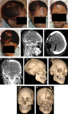
Preoperative photographs and radiographic imaging of the sentinel patient presenting for cranioplasty. A-D, Preoperative photographs of the patient in lateral, oblique, frontal, and bird's eye views. The red circle in each photograph denotes the area of brain herniation from the craniectomy defect. E-G, Representative CT scan images of the brain after decompressive hemicraniectomy and suboccipital craniectomy (sagittal, axial, and coronal views, respectively). Note the large hemicraniectomy defect, with cystic encephalomalacia within the herniated brain parenchyma, as well as subdural hygroma. Also note the extensive metallic debris from the retained bullet in the right occipital lobe and frontoparietal lobe. H-K, 3-D CT reconstruction imaging used for designing CCI. Note the hemicraniectomy defect, as well as the smaller suboccipital craniectomy defect visible from the posterior view K.
FIGURE 2.
FIGURE 2.
Virtual surgical planning images based on 3D-CT scans for CCI creation. The implant is fabricated from translucent PMMA in a computer-assisted process (4-mm thickness for this specific patient) then sterilized prior to implantation. The proposed implant design is shown in blue on each image. A, Coronal view; B, oblique view; C, horizontal view; and D, lateral view.
FIGURE 3.
FIGURE 3.
Select intraoperative photographs. A, Note the large right-sided hemicraniectomy defect and extracranial parenchymal herniation. The black dashed-line surgical markings demonstrate the palpable cranial defect. The solid black line is an outline of the previous scalp incision. Note that if the previous scalp incision was utilized, it would be directly overlying the defect and hence the implant. As such, a new incision was designed parallel to the defect to allow the implant to be completely covered by healthy scalp (incision demonstrated by red line). Despite historical concerns that parallel scalp incisions may cause vascular necrosis of the skin bridge, in our experience, we have not found this to be the case in scalp flaps. The translucent PMMA CCI was preplated on the back table, and a handheld burr used to create a recess for countersinking of the ICP sensor, as shown B. After the scalp was elevated such that a pericranial-onlay flap remained over the dura, the LID-ICP was secured in place with titanium hardware C.
FIGURE 4.
FIGURE 4.
Intraoperative photograph of handheld monitoring device and wireless wand being employed at completion of cranioplasty reconstruction A. Of note, the display screen shows an intraoperative ICP measurement of 7 mmHg following manual brain reduction, cranial implant placement, and complex scalp closure B.
FIGURE 5.
FIGURE 5.
Postoperative photographs and relevant imaging. A-D, Postoperative photographs showing improved cranial contour despite visible ICP monitoring device (red arrows). E-G, Representative sagittal, coronal, and axial postoperative CT scan images of the brain showing decrease in intraparenchymal cyst. Also note the positioning of the ICP sensor within the brain and the improved cranial contour provided by the implant. H-K, Postoperative 3D-CT reconstruction showing device placement, although the translucent CCI is not readily apparent in this view. Also visible are the subgaleal suction drains utilized as part of our standard cranioplasty technique (removed on postoperative days 2 and 3 before the patient is discharged to home).
FIGURE 6.
FIGURE 6.
Trending graph depicting ICP measurements in supine (0 degree, blue dashed line) and sitting (30 degree, red dotted line) positions from 1 to 36 h postcranioplasty. The first measurements were obtained 1 h after the patient was extubated. Note that even at this acute time point, there is postural ICP difference (black solid line). At 2 wk postcranioplasty in the outpatient clinic setting (not shown on graph), ICP measured 10 mmHg sitting and 4 mmHg supine, which is similar to the values shown here.

References

    1. Dewan MC, Rattani A, Gupta Set al.. Estimating the global incidence of traumatic brain injury. J Neurosurg. 2018;130(4):1039-1408. - PubMed
    1. Hutchinson PJ, Kolias AG, Timofeev ISet al.. Trial of decompressive craniectomy for traumatic intracranial hypertension. N Engl J Med. 2016;375(12):1119-1130. - PubMed
    1. Sahuquillo J, Arikan F. Decompressive craniectomy for the treatment of refractory high intracranial pressure in traumatic brain injury. Cochrane Database Syst Rev. 2006(1):CD003983. - PubMed
    1. Badri S, Chen J, Barber Jet al.. Mortality and long-term functional outcome associated with intracranial pressure after traumatic brain injury. Intensive Care Med. 2012;38(11):1800-1809. - PubMed
    1. Timofeev I, Santarius T, Kolias AG, Hutchinson PJ. Decompressive craniectomy - operative technique and perioperative care. Adv Tech Stand Neurosurg. 2012;38:115-136. - PubMed