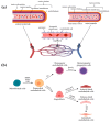
Blood and Lymphatic Vasculatures On-Chip Platforms and Their Applications for Organ-Specific In Vitro Modeling
- PMID: 32013154
- PMCID: PMC7074693
- DOI: 10.3390/mi11020147
Blood and Lymphatic Vasculatures On-Chip Platforms and Their Applications for Organ-Specific In Vitro Modeling
Abstract
The human circulatory system is divided into two complementary and different systems, the cardiovascular and the lymphatic system. The cardiovascular system is mainly concerned with providing nutrients to the body via blood and transporting wastes away from the tissues to be released from the body. The lymphatic system focuses on the transport of fluid, cells, and lipid from interstitial tissue spaces to lymph nodes and, ultimately, to the cardiovascular system, as well as helps coordinate interstitial fluid and lipid homeostasis and immune responses. In addition to having distinct structures from each other, each system also has organ-specific variations throughout the body and both systems play important roles in maintaining homeostasis. Dysfunction of either system leads to devastating and potentially fatal diseases, warranting accurate models of both blood and lymphatic vessels for better studies. As these models also require physiological flow (luminal and interstitial), extracellular matrix conditions, dimensionality, chemotactic biochemical gradient, and stiffness, to better reflect in vivo, three dimensional (3D) microfluidic (on-a-chip) devices are promising platforms to model human physiology and pathology. In this review, we discuss the heterogeneity of both blood and lymphatic vessels, as well as current in vitro models. We, then, explore the organ-specific features of each system with examples in the gut and the brain and the implications of dysfunction of either vasculature in these organs. We close the review with discussions on current in vitro models for specific diseases with an emphasis on on-chip techniques.
Keywords: blood vessels; brains; disease models-on-a-chip platforms; in vitro models; intestines; lymphatic vessels; micro-physiological systems; organ specificity; vasculatures-on-a-chip platforms.
Conflict of interest statement
The authors declare no conflict of interest.
Figures


Similar articles
-
Lymphatic Tissue and Organ Engineering for In Vitro Modeling and In Vivo Regeneration.Cold Spring Harb Perspect Med. 2022 Mar 14;12(9):a041169. doi: 10.1101/cshperspect.a041169. Online ahead of print. Cold Spring Harb Perspect Med. 2022. PMID: 35288402 Free PMC article.
-
In Vitro Models of Blood and Lymphatic Vessels-Connecting Tissues and Immunity.Adv Biol (Weinh). 2023 May;7(5):e2200041. doi: 10.1002/adbi.202200041. Epub 2022 Jun 25. Adv Biol (Weinh). 2023. PMID: 35751460 Free PMC article. Review.
-
Interaction Between Blood Vasculatures and Lymphatic Vasculatures During Inflammation.J Inflamm Res. 2023 Aug 4;16:3271-3281. doi: 10.2147/JIR.S414891. eCollection 2023. J Inflamm Res. 2023. PMID: 37560514 Free PMC article. Review.
-
Engineered models of the lymphatic vascular system: Past, present, and future.Microcirculation. 2023 Apr;30(2-3):e12793. doi: 10.1111/micc.12793. Epub 2022 Dec 5. Microcirculation. 2023. PMID: 36415150 Review.
-
Go with the flow: modeling unique biological flows in engineered in vitro platforms.Lab Chip. 2021 Jun 1;21(11):2095-2120. doi: 10.1039/d1lc00014d. Lab Chip. 2021. PMID: 34008661 Review.
Cited by
-
Engineering approaches to investigate the roles of lymphatics vessels in rheumatoid arthritis.Microcirculation. 2023 Apr;30(2-3):e12769. doi: 10.1111/micc.12769. Epub 2022 Jun 6. Microcirculation. 2023. PMID: 35611452 Free PMC article. Review.
-
Cellular Crosstalk between Endothelial and Smooth Muscle Cells in Vascular Wall Remodeling.Int J Mol Sci. 2021 Jul 6;22(14):7284. doi: 10.3390/ijms22147284. Int J Mol Sci. 2021. PMID: 34298897 Free PMC article. Review.
-
Advances in the Model Structure of In Vitro Vascularized Organ-on-a-Chip.Cyborg Bionic Syst. 2024 Apr 25;5:0107. doi: 10.34133/cbsystems.0107. eCollection 2024. Cyborg Bionic Syst. 2024. PMID: 40353137 Free PMC article.
-
Bioengineering for vascularization: Trends and directions of photocrosslinkable gelatin methacrylate hydrogels.Front Bioeng Biotechnol. 2022 Nov 17;10:1053491. doi: 10.3389/fbioe.2022.1053491. eCollection 2022. Front Bioeng Biotechnol. 2022. PMID: 36466323 Free PMC article. Review.
-
An update on oral drug delivery via intestinal lymphatic transport.Acta Pharm Sin B. 2021 Aug;11(8):2449-2468. doi: 10.1016/j.apsb.2020.12.022. Epub 2021 Apr 9. Acta Pharm Sin B. 2021. PMID: 34522594 Free PMC article. Review.
References
-
- Dallinga M.G., Boas S.E.M., Klaassen I., Merks R.H.M., van Noorden C.J.F., Schlingemann R.O. eLS. John Wiley & Sons, Ltd.; Hoboken, NJ, USA: 2015. Tip Cells in Angiogenesis; pp. 1–10.
Publication types
Grants and funding
LinkOut - more resources
Full Text Sources
Research Materials

