Prediction of mechanical hemolysis in medical devices via a Lagrangian strain-based multiscale model
- PMID: 32017130
- PMCID: PMC7387140
- DOI: 10.1111/aor.13663
Prediction of mechanical hemolysis in medical devices via a Lagrangian strain-based multiscale model
Abstract
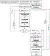
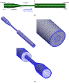
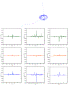
This work introduces a new Lagrangian strain-based model to predict the shear-induced hemolysis in biomedical devices. Current computational models for device-induced hemolysis usually utilize empirical fitting of the released free hemoglobin (Hb) in plasma from damaged red blood cells (RBCs). These empirical correlations contain parameters that depend on specific device and operating conditions, thus cannot be used to predict hemolysis in a general device. The proposed algorithm does not have any empirical parameters, thus can presumably be used for hemolysis prediction in various blood-wetting medical devices. In contrast to empirical correlations in which the Hb release is related to the shear stress and exposure time without considering the physical processes, the proposed model links flow-induced deformation of the RBC membrane to membrane permeabilization and Hb release. In this approach, once the steady-state numerical solution of blood flow in the device is obtained under a prescribed operating condition, sample path lines are traced from the inlet of the device to the outlet to calculate the history of the shear stress tensor. In solving the fluid flow, it is assumed that RBCs do not have any influence on the flow pattern. Along each path line, shear stress tensor will be input into a coarse-grained (CG) RBC model to calculate the RBC deformation. Then the correlations obtained from molecular dynamics (MD) simulations are applied to relate the local areal RBC deformation to the perforated area on the RBC membrane. Finally, Hb released out of transient pores is calculated over each path line via a diffusion equation considering the effects of the steric hindrance and increased hydrodynamic drag due to the size of the Hb molecule. The total index of hemolysis (IH) is calculated by integration of released Hb over all the path lines in the computational domain. Hemolysis generated in the Food and Drug Administration (FDA) nozzle and two blood pumps, that is, a CentriMag blood pump (a centrifugal pump) and HeartMate II (an axial pump), for different flow regimes including the laminar and turbulent flows are calculated via the proposed algorithm. In all the simulations, the numerical predicted IH is close to the range of experimental data. The results promisingly indicate that this multiscale approach can be used as a tool for predicting hemolysis and optimizing the hematologic design of other types of blood-wetting devices.
Keywords: FDA nozzle; Lagrangian strain-based model; axial pump; centrifugal pump; mechanical hemolysis; multiscale modeling.
© 2020 International Center for Artificial Organs and Transplantation and Wiley Periodicals, Inc.
Figures


Similar articles
-
Multiscale modeling of hemolysis during microfiltration.Microfluid Nanofluidics. 2020 May;24(5):33. doi: 10.1007/s10404-020-02337-3. Epub 2020 Apr 10. Microfluid Nanofluidics. 2020. PMID: 33235552 Free PMC article.
-
Large-Eddy Simulations of Flow in the FDA Benchmark Nozzle Geometry to Predict Hemolysis.Cardiovasc Eng Technol. 2020 Jun;11(3):254-267. doi: 10.1007/s13239-020-00461-3. Epub 2020 Apr 15. Cardiovasc Eng Technol. 2020. PMID: 32297154 Free PMC article.
-
Hemolysis estimation in turbulent flow for the FDA critical path initiative centrifugal blood pump.Biomech Model Mechanobiol. 2021 Oct;20(5):1709-1722. doi: 10.1007/s10237-021-01471-3. Epub 2021 Jun 9. Biomech Model Mechanobiol. 2021. PMID: 34106362
-
A Review of Hemolysis Prediction Models for Computational Fluid Dynamics.Artif Organs. 2017 Jul;41(7):603-621. doi: 10.1111/aor.12871. Epub 2017 Jun 23. Artif Organs. 2017. PMID: 28643335 Review.
-
Modeling and prediction of flow-induced hemolysis: a review.Biomech Model Mechanobiol. 2019 Aug;18(4):845-881. doi: 10.1007/s10237-019-01137-1. Epub 2019 Mar 7. Biomech Model Mechanobiol. 2019. PMID: 30847662 Review.
Cited by
-
Coarse-Grained Modeling of Pore Dynamics on the Red Blood Cell Membrane under Large Deformations.Biophys J. 2020 Aug 4;119(3):471-482. doi: 10.1016/j.bpj.2020.06.016. Epub 2020 Jun 24. Biophys J. 2020. PMID: 32645292 Free PMC article.
-
Flow simulation-based particle swarm optimization for developing improved hemolysis models.Biomech Model Mechanobiol. 2023 Apr;22(2):401-416. doi: 10.1007/s10237-022-01653-7. Epub 2022 Nov 28. Biomech Model Mechanobiol. 2023. PMID: 36441414 Free PMC article.
-
A cell-resolved, Lagrangian solver for modeling red blood cell dynamics in macroscale flows.J Comput Phys. 2022 Jul 15;461:111204. doi: 10.1016/j.jcp.2022.111204. Epub 2022 Apr 8. J Comput Phys. 2022. PMID: 36275186 Free PMC article.
-
Tannic acid-loaded zinc- and copper-doped mesoporous bioactive glass nanoparticles: Potential antioxidant nanocarriers for wound healing.Bioact Mater. 2025 Aug 12;54:71-85. doi: 10.1016/j.bioactmat.2025.07.046. eCollection 2025 Dec. Bioact Mater. 2025. PMID: 40831706 Free PMC article.
-
Investigating the effect of turbulence on hemolysis through cell-resolved fluid-structure interaction simulations of individual red blood cells.Phys Rev Fluids. 2024 Jul;9(7):073102. doi: 10.1103/physrevfluids.9.073102. Epub 2024 Jul 26. Phys Rev Fluids. 2024. PMID: 40018510 Free PMC article.
References
-
- Schumacher JT, Grodrian A, Lemke K, Römer R, and Metze J, “System development for generating homogeneous cell suspensions and transporting them in microfluidic devices,” Eng. Life Sci, vol. 8, no. 1, pp. 49–55, 2008.
-
- Throckmorton AL et al., “Numerical, hydraulic, and hemolytic evaluation of an intravascular axial flow blood pump to mechanically support fontan patients,” Ann. Biomed. Eng, vol. 39, no. 1, pp. 324–336, 2011. - PubMed
-
- Castellini P, Pinotti M, and Scalise L, “Particle image velocimetry for flow analysis in longitudinal planes across a mechanical artificial heart valve,” Artif. Organs, vol. 28, no. 5, pp. 507–513, 2004. - PubMed
-
- Nair K et al., “Characterization of cell viability during bioprinting processes,” Biotechnol. J, vol. 4, no. 8, pp. 1168–1177, 2009. - PubMed
-
- Rother RP, Bell L, Hillmen P, and Gladwin MT, “The clinical sequelae of intravascular hemolysis and extracellular plasma hemoglobin: A novel mechanism of human disease,” Journal of the American Medical Association, vol. 293, no. 13 pp. 1653–1662, 2005. - PubMed
MeSH terms
Substances
Grants and funding
LinkOut - more resources
Full Text Sources

