Review
. 2019 Dec 11;7(3):1902590.
doi: 10.1002/advs.201902590. eCollection 2020 Feb.

Electrospinning of Metal-Organic Frameworks for Energy and Environmental Applications

Affiliations
Review

Electrospinning of Metal-Organic Frameworks for Energy and Environmental Applications

Yibo Dou et al. Adv Sci (Weinh). .

Abstract

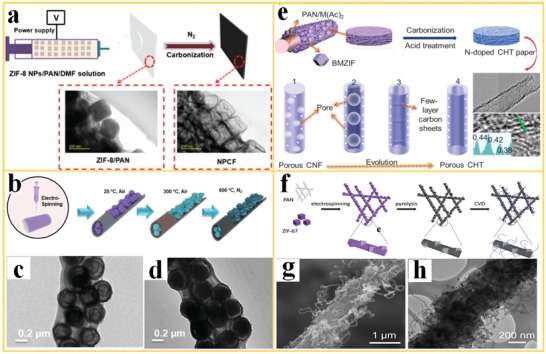
Herein, recent developments of metal-organic frameworks (MOFs) structured into nanofibers by electrospinning are summarized, including the fabrication, post-treatment via pyrolysis, properties, and use of the resulting MOF nanofiber architectures. The fabrication and post-treatment of the MOF nanofiber architectures are described systematically by two routes: i) the direct electrospinning of MOF-polymer nanofiber composites, and ii) the surface decoration of nanofiber structures with MOFs. The unique properties and performance of the different types of MOF nanofibers and their derivatives are explained in respect to their use in energy and environmental applications, including air filtration, water treatment, gas storage and separation, electrochemical energy conversion and storage, and heterogeneous catalysis. Finally, challenges with the fabrication of MOF nanofibers, limitations for their use, and trends for future developments are presented.

Keywords: electrospinning; energy and environmental applications; hierarchical porous structure; metal–organic frameworks.


Conflict of interest statement

The authors declare no conflict of interest.

Figures

Figure 1
Figure 1
Schematic illustration of the potential use of MOF nanofibers in various energy and environmental applications.
Figure 2
Figure 2
The direct electrospinning of MOF‐polymer composite nanofibers: a) Electrospinning of ZIF‐8‐PVP nanofiber layer on a porous SiO2 support (as seeds for further in situ growth of a MOF membrane). b,c) SEM images of the ZIF‐8 crystallites embedded in the PVP nanofibers, with mass fraction of 6 and 12 wt%. Reproduced with permission.65 Copyright 2012, Royal Society of Chemistry. d) A schematic for the mixing steps of metal ion and organic ligand precursor solution for electrospinning of freestanding ZIF‐7/PAN nanofibers and e,f) the resulting microstructures by SEM and TEM images. Reproduced with permission.68 Copyright 2016, Wiley‐VCH. g) Different types of MOFs with different functionalities, investigated for the use in MOF‐polymer nanofiber layers and h) photos and SEM images of different MOF‐nanofiber composites after electrospinning. Reproduced with permission.69 Copyright 2016, American Chemical Society.
Figure 3
Figure 3
Electrospinning and post‐treatment approaches to create porosity in MOF‐polymer nanofibers: a) Fast solvent evaporation during electrospinning of PLA/ZIF‐8 nanofibers. Reproduced with permission.70 Copyright 2018, Elsevier. b) Selective removal of PEO polymer from ZIF‐8/matrimid‐PEO nanofibers by using solvent extraction. c) N2 isotherms for different ratios of Mat:PEO:ZIF‐8 in the “as‐synthesized” nanofibers and after PEO removal (“washed”). Reproduced with permission.71 Copyright 2017, American Chemical Society.
Figure 4
Figure 4
In situ growth approaches for the fabrication of MOF nanofibers. a) The growth of MOF crystals on polymer nanofibers with embedded MOF seeds. Reproduced with permission.55 Copyright 2012, Royal Society of Chemistry. b) Incorporation of metal ions (as Co(Ac)2) into PAN polymer nanofibers during electrospinning to enable the growth of ZIF‐67 on the nanofibers. Reproduced with permission.81 Copyright 2018, Royal Society of Chemistry. c) Addition of an organic linker (ATA) into PAN nanofibers during electrospinning for growth of UiO‐66‐NH2‐PAN nanofibers with improved MOF adherence and loading (scale bar is 3 µm). Reproduced with permission.83 Copyright 2017, American Chemical Society. d) Cross‐linking of PVCi via UV irradiation for stabilization of polymer nanofibers to enable MOF growth under solvothermal conditions. Reproduced with permission.51 Copyright 2015, American Chemical Society. e) Core–shell structure with an ultrathin ALD coating of TiO2 on PA‐6 nanofibers to enable the growth of Zr‐MOF with SEM images of resulting PA‐6@TiO2@UiO‐66‐NH2 nanofibers. Reproduced with permission.92 Copyright 2016, Wiley‐VCH.
Figure 5
Figure 5
Phase conversion in the preparation of MOF nanofibers: a) Processing steps for the solvothermal conversion of metal oxide nanofibers into flexible self‐supported MOF nanofiber mats and b) different types of metal oxides that have been converted into MOF nanofibers by phase conversion and the corresponding SEM images of the microstructures (scale bar is 2 µm). Reproduced with permission.93 Copyright 2018, Royal Society of Chemistry. c,d) The SEM images of ZnO nanofibers and the corresponding ZIF‐8 nanofibers after gas phase transformation. e,f) TEM images of the ZnO/ZIF‐8 nanofibers after treatment at 150 and 200 °C. Reproduced with permission.95 Copyright 2018, Elsevier.
Figure 6
Figure 6
The processing and microstructure of derivatives of MOF nanofibers. a) Electrospinning and carbonization of ZIF‐8/PAN nanofibers into nanoporous carbon nanofibers (NPCF) and the respective TEM images. Reproduced with permission.96 Copyright 2018, Royal Society of Chemistry. b) The fabrication step to fabricate ysMnOx@NC, and the TEM images of c) preoxidized Mn‐BTC@PAN and d) ysMnOx@NC annealed at 600 °C. Reproduced with permission.97 Copyright 2019, Wiley‐VCH. e) CHTs with a large fraction of surface graphitization, including TEM image for the visualization of the enlarged d‐spacing. Reproduced with permission.98 Copyright 2017, Cell Press. f) Hierarchical porous carbon nanofibers and its g) SEM and h) TEM images showing the details of the microstructure with the CNF skeleton, including porous hollow carbon cube fillers, and CNTs attached to the surface. Reproduced with permission.99 Copyright 2018, Royal Society of Chemistry.
Figure 7
Figure 7
MOF nanofibers in air filtration. a) Proposed PM capture mechanism (inset: the SEM image of MOF nanofiber). b) SO2 dynamic adsorption on various type of filters. c) A photo of portable electrospinning device for deposition of MOF filters directly on a glove. Reproduced with permission.69 Copyright 2016, American Chemical Society. d) PM filtration efficiencies of MIL‐53(Al), 50%‐MIL‐53(Al)/Al2O3, and Al2O3 fibrous mats. e) Long‐term PM2.5 filtration efficiencies of the MIL‐53(Al) fibrous mats. Reproduced with permission.93 Copyright 2018, Royal Society of Chemistry. f) The air filtration performance of CFs@ZIF‐8 nanofiber filter (the white and black columns represent the filtration efficiency and the pressure drop, respectively). Reproduced with permission.104 Copyright 2018, Springer.
Figure 8
Figure 8
MOF‐polymer nanofibers for water treatment. a) Pb(II) uptake capacity of MOF‐PVA composite nanofibers. b) The comparison of maximum Pb(II) uptake capacities of different filter materials. Reproduced with permission.109 Copyright 2016, Springer. c) Adsorption of U(VI) ions on ZIF‐8 particles in ZIF‐8/PAN filters and d) the U(VI) removal rate for different filter materials. Reproduced with permission.110 Copyright 2018, American Chemical Society. e) Fabrication of PAN@ZIF‐8 membranes and the selective separation of oil/water mixtures and emulsions. Reproduced with permission.116 Copyright 2017, Elsevier.
Figure 9
Figure 9
MOF‐polymer nanofibers in gas storage and separation. a) H2 sorption isotherms for pristine Zr‐MOF nanocrystals and Zr‐MOF nanofiber. Reproduced with permission.120 Copyright 2015, Elsevier. b) Separation performance of ZIF‐8 nanofiber for a 1:1 mixture of N2/CO2 as feed gas. Reproduced with permission.55 Copyright 2012, Royal Society of Chemistry.
Figure 10
Figure 10
MOF nanofibers and derivatives used in electrochemical energy storage and conversion. a) Illustration of the fabrication steps of CNT/Co3O4 microtubes with I) the growth of ZIF‐67 onto the PAN‐Co(Ac)2 nanofiber and II) removal of the PAN‐Co(Ac)2 core. III) Heating treatment to convert ZIF‐67 tubular structures into CNT/Co‐carbon composite and IV) calcination to obtain the CNT/Co3O4 microtubes. b) Cycling performance and coulombic efficiency. Reproduced with permission.124 Copyright 2016, Wiley‐VCH. c) MOF‐PVA nanofiber used as separator for adsorbing anions and facilitating the transport of lithium ions. Reproduced with permission.18 Copyright 2019, Wiley‐VCH. d) Schematic illustration of the fabrication of ZPCNF and its e) CV curves and f) GCD curves. Reproduced with permission.127 Copyright 2017, Royal Society of Chemistry. g) A schematic of proton‐conduction in oriented MOF nanofibers and a TEM image of the structure. Reproduced with permission.128 Copyright 2014, Nature.
Figure 11
Figure 11
The derivatives of MOF nanofibers used in electrocatalysis. a) Schematic of the preparation and structure of ZCP‐CNF derived from ZnCo‐ZIF/PAN nanofiber for ORR. b,c) Polarization curves and kinetic‐limiting current density of various electrocatalysts. Reproduced with permission.131 Copyright 2017, Royal Society of Chemistry. d) Carbonization of a ZIF‐8/polymer nanofiber into a hierarchical porous, worm‐like CNF architecture with multi‐heteroatom doping for use in ORR. Reproduced with permission.133 Copyright 2017, American Chemical Society. e) The fabrication of a CoNC@MoS2/CNF hybrid material as bifunctional HER and OER electrocatalyst. f,g) Performance of the hybrid material with polarization curves.86 Copyright 2017, Royal Society of Chemistry. h) Discharging polarization curves and corresponding power plots and i) voltage–capacity curves of derivative of Co‐ZIF‐L/PAN nanofibers for a noble‐metal‐based Zn‐air battery. Adapted with permission.73 Copyright 2019, Wiley‐VCH.
Figure 12
Figure 12
MOF nanofibers in heterogeneous catalysis. a) A schematic of electrospinning, structure, and reaction of ZIF‐67/PAN nanofibers in oxidative decomposition of organic pollutants, showing the activation of peroxymonosulfate and generation of sulfate radicals. b) Decolorization of AY using ZIF‐67/PAN via adsorption, c) PMS activation and yellow‐17 (AY) pollutant degradation on PAN, ZIF‐67, and ZIF‐67/PAN nanofibers. Reproduced with permission.138 Copyright 2017, Elsevier. d) The schematic representation of the use of BIT‐58 in the catalytic reaction of benzaldehyde to 2‐benzylidenemalononitrile and e) photo and SEM images of the nano‐BIT‐58/PAN nanofiber. f) Catalytic performance of BIT‐58 and nano‐BIT‐58. g) Catalytic performances of the film during three catalytic cycles. Reproduced with permission.139 Copyright 2018, Royal Society of Chemistry. h) PA‐6@TiO2@UiO‐66 nanofiber used for the degradation of highly toxic CWAs. Reproduced with permission.140 Copyright 2017, American Chemical Society. i) TEM images of a PA‐6@TiO2@UiO‐67 nanofiber. j) Conversion of nerve agent soman (GD) using Zr‐MOFs nanofiber versus reaction time. Reproduced with permission.92 Copyright 2016, Wiley‐VCH.
Figure 13
Figure 13
MOF nanofibers used in heterogeneous catalysis. a) Pt@MIL‐101 embedded in a PCL matrix as a “catalytic carpet” for highly efficient catalysis. b) The conversion of cyclohexene to cyclohexane using Pt@MIL‐101/PCL and Pt@MIL‐101 as a catalyst. Reproduced with permission.22 Copyright 2018, Elsevier. c) The Knoevenagel condensation of benzaldehyde with malononitrile catalyzed by MIL‐53(Al)‐NH2. d,e) Time–yield plots and yields at different runs of the catalysis by the MOF nanofiber and powder. f) Illustration of the plug‐flow reactor. g) Time‐dependent yield at different cycles catalyzed by the MOF nanofiber and powder in a plug‐flow reactor. Reproduced with permission.93 Copyright 2018, Royal Society of Chemistry.

References

    1. Chu S., Majumdar A., Nature 2012, 488, 294. - PubMed
    1. Bushuyev O. S., Luna P. D., Dinh C. T., Tao L., Saur G., Lagemaat J., Kelley S. O., Sargent E. H., Joule 2018, 2, 825.
    1. Heald C. L., Spracklen D. V., Chem. Rev. 2015, 115, 4476. - PubMed
    1. Waske A., Dzekan D., Sellschopp K., Berger D., Stork A., Nielsch K., Fähler S., Energy Environ. Sci. 2019. 12, 1019.
    1. Heard C. J., Čejka J., Opanasenko M., Nachtigall P., Centi G., Perathoner S., Adv. Mater. 2018, 31, 1801712. - PubMed

LinkOut - more resources