. 2020 Mar;21(3):75-86.
doi: 10.1002/acm2.12827. Epub 2020 Feb 11.

Standardized flattening filter free volumetric modulated arc therapy plans based on anteroposterior width for total body irradiation

Affiliations

Standardized flattening filter free volumetric modulated arc therapy plans based on anteroposterior width for total body irradiation

Rebecca Frederick et al. J Appl Clin Med Phys. 2020 Mar.

Abstract

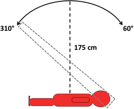
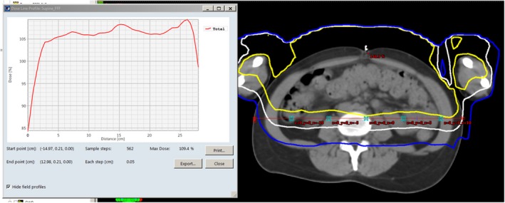
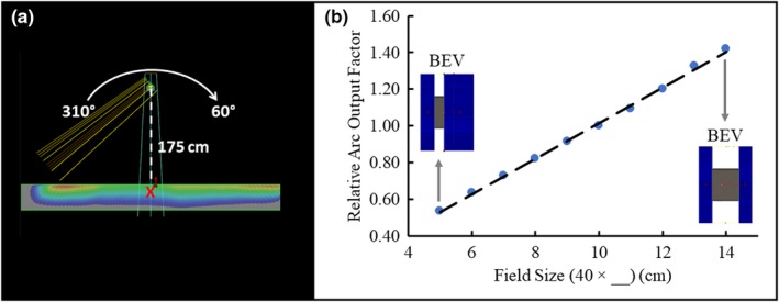
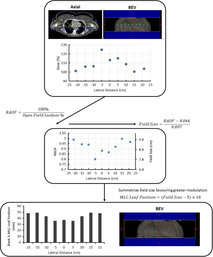
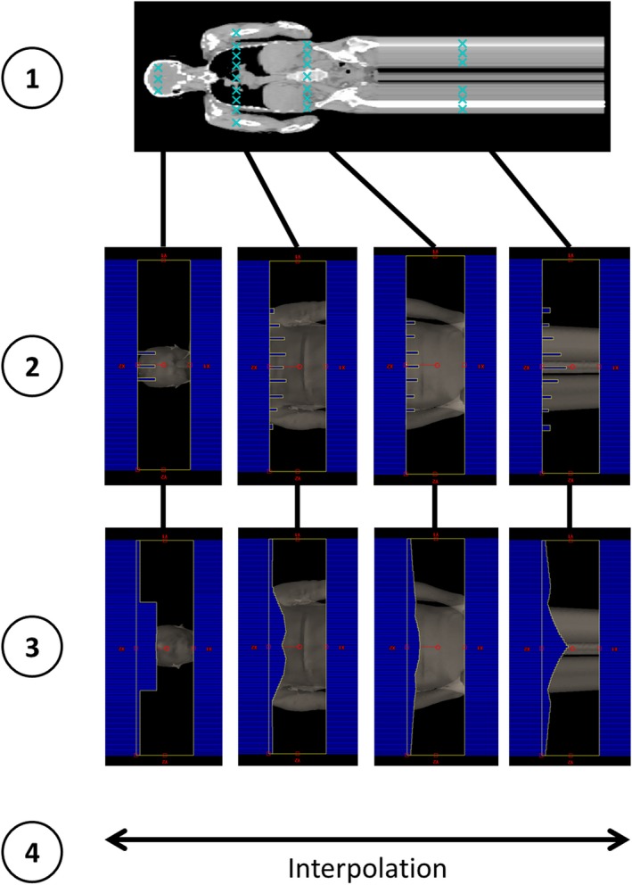
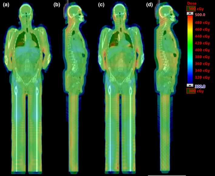
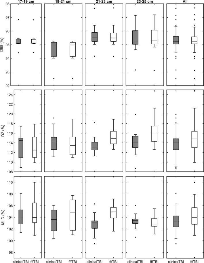
In this work, the feasibility of using flattening filter free (FFF) beams in volumetric modulated arc therapy (VMAT) total body irradiation (TBI) treatment planning to decrease protracted beam-on times for these treatments was investigated. In addition, a methodology was developed to generate standardized VMAT TBI treatment plans based on patient physical dimensions to eliminate plan optimization time. A planning study cohort of 47 TBI patients previously treated with optimized VMAT ARC 6 MV beams was retrospectively examined. These patients were sorted into six categories depending on height and anteroposterior (AP) width at the umbilicus. Using Varian Eclipse, clinical 40 cm × 10 cm open field arcs were substituted with 6 MV FFF. Mid-plane lateral dose profiles in conjunction with relative arc output factors (RAOF) yielded how far a given multileaf collimator (MLC) leaf must move in order to achieve a mid-plane 100% isodose for a specific control point. Linear interpolation gave the dynamic MLC aperture for the entire arc for each patient AP width category, which was subsequently applied through Python scripting. All FFF VMAT TBI plans were then evaluated by two radiation oncologists and deemed clinically acceptable. The FFF and clinical VMAT TBI plans had similar Body-5 mm D98% distributions, but overall the FFF plans had statistically significantly increased or broader Body-5 mm D2% and mean lung dose distributions. These differences are not considered clinically significant. Median beam-on times for the FFF and clinical VMAT TBI plans were 11.07 and 18.06 min, respectively, and planning time for the FFF VMAT TBI plans was reduced by 34.1 min. In conclusion, use of FFF beams in VMAT TBI treatment planning resulted in dose homogeneity similar to our current VMAT TBI technique. Clinical dosimetric criteria were achieved for a majority of patients while planning and calculated beam-on times were reduced, offering the possibility of improved patient experience.

Keywords: flattening filter free; total body irradiation; treatment planning; treatment technique comparison; volumetric modulated arc therapy.


Conflict of interest statement

The authors have no relevant conflict of interest to disclose.

Figures

Figure 1
Figure 1
A schematic of the clinical VMAT TBI technique used as the basis of the FFF VMAT TBI technique. The gantry arcs over the patient 7‐8 times between gantry angles 310° and 60° (IEC 601) with the patient at an extended SSD of approximately 175 cm. The patient is treated in both the supine (shown) and prone orientations. FFF, flattening filter free; TBI, total body irradiation; VMAT, volumetric modulated arc therapy.
Figure 2
Figure 2
A coronal patient CT image with the nine cranial‐caudal locations where lateral dose profiles were collected to compute MLC modulation indicated by horizontal lines. Spacing between locations is indicated to the right of the image. MLC, multileaf collimator.
Figure 3
Figure 3
A screen capture from Eclipse of an axial CT slice of a patient at the level of the umbilicus with a supine open field 6 MV FFF VMAT TBI plan applied. On the right is the CT image with the 110% isodose level in yellow, the 100% isodose level in white, and the 90% isodose level in blue. The mid‐plane red line on the CT image indicates the location of the dose profile, with the profile itself presented on the left. The crosses along the mid‐plane red line on the CT image are reference points. FFF, flattening filter free; TBI, total body irradiation; VMAT, volumetric modulated arc therapy.
Figure 4
Figure 4
An illustration of the Eclipse setup and the RAOF curve. (a) RAOFs were modeled in a simulated 20 cm × 30 cm × 200 cm water phantom at an extended SSD of 175 cm in Eclipse. Arc energy, angles, and meterset weights matched those used for the FFF VMAT TBI plans. RAOFs for MLC‐defined fields between 40 cm × 5 cm and 40 cm × 14 cm were determined at 5 cm depth directly below isocenter (red cross). (b) The RAOF curve is normalized to a field size of 10 cm. The x‐axis describes the change in field size associated with the MLC. The Y‐jaw was static at 40 cm. The dashed line illustrates the linear fit used for MLC modulation calculation. Two beam's eye view (BEV) images of the MLC‐defined aperture are shown for the 40 cm × 5 cm and 40 cm × 14 cm measurements. FFF, flattening filter free; MLC, multileaf collimator; RAOF, relative arc output factor; TBI, total body irradiation; VMAT, volumetric modulated arc therapy.
Figure 5
Figure 5
An example of MLC leaf position calculation at a single cranial‐caudal location. A discrete lateral dose profile as shown in the axial and beam's eye view (BEV) images is averaged from the dose data of three patients from each category. The RAOF equation (Equation 1) is then applied to each point. The required field size is then calculated at each point using the linear fit from Fig. 4 (Equation 2). In order to keep the standard plans more generalized, the field size is symmetrized over the patient's lateral mid‐line (x = 0 cm), favoring the larger field size changes. Finally, the MLC leaf position coded into the plan DICOM file is calculated. These positions correspond to those in the BEV shown next to the bar graph. MLC, multileaf collimator; RAOF, relative arc output factor.
Figure 6
Figure 6
An illustration of the process of MLC aperture generation at four example cranial‐caudal locations. Step 1 is the collection of discrete AP mid‐plane dose profiles from the four locations. Application of the RAOF curve and trigonometric translation for the discrete profiles results in the beam's eye view MLC apertures shown in Step 2. The final MLC positions in Step 3 are produced by laterally interpolating the shapes from Step 2. A full VMAT arc is achieved by interpolating between the apertures shown in Step 3. MLC, multileaf collimator; RAOF, relative arc output factor; VMAT, volumetric modulated arc therapy.
Figure 7
Figure 7
CT data of single coronal and sagittal slices from the same patient in the 21‐23 cm Tall categorization with dose color washes corresponding to each TBI plan. (a) and (b) show the clinical plan dose wash (clinicalTBI), and (c) and (d) the standard FFF plan dose wash (fffTBI).
Figure 8
Figure 8
The dose‐volume histogram (DVH) parameter distributions of the clinical (clinicalTBI) and FFF (fffTBI) TBI plans for each patient categorization. The DVH parameters shown for all categories include the Body–5 mm D98% (top) and D2% (middle), and mean lung dose (MLD) (bottom). Each box moving left to right corresponds to the AP width categories in increasing order, ending with the data for all patients.

Similar articles

Cited by

References

    1. Russell JA, Irish W, Balogh A, et al. The addition of 400 cGy total body irradiation to a regimen incorporating once‐daily intravenous busulfan, fludarabine, and antithymocyte globulin reduces relapse without affecting nonrelapse mortality in acute myelogenous leukemia. Biol Blood Marrow Transplant. 2010;16:509–514. - PubMed
    1. Thomas O, Mahé M‐A, Campion L, et al. Long‐term complications of total body irradiation in adults. Int J Radiat Oncol. 2001;49(1):125–131. - PubMed
    1. Studinski RCN, Fraser DJ, Samant RS, Macpherson MS. Current practice in total‐body irradiation: results of a Canada‐wide survey. Curr Oncol. 2017;24(3):181–186. - PMC - PubMed
    1. Van Dyk J, Galvin JM, Glasgow JP, Podgorsak EB. The Physical Aspects of Total and a Half Body Photon Irradiation. AAPM Report No 17. New York, NY: American Institute of Physics; 1986.
    1. Khan FM, Gibbons JP. Khan's the Physics of Radiation Therapy. 5th ed Philadelphia, PA: Lippincott Williams & Wilkins; 2014.

MeSH terms