

Radiation damage and dose limits in serial synchrotron crystallography at cryo- and room temperatures
- PMID: 32047034
- PMCID: PMC7049125
- DOI: 10.1073/pnas.1821522117
Radiation damage and dose limits in serial synchrotron crystallography at cryo- and room temperatures
Abstract
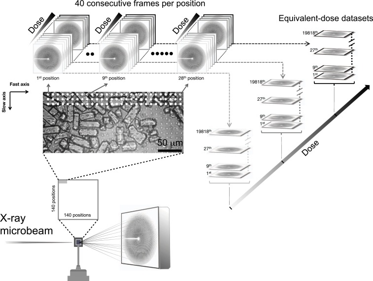
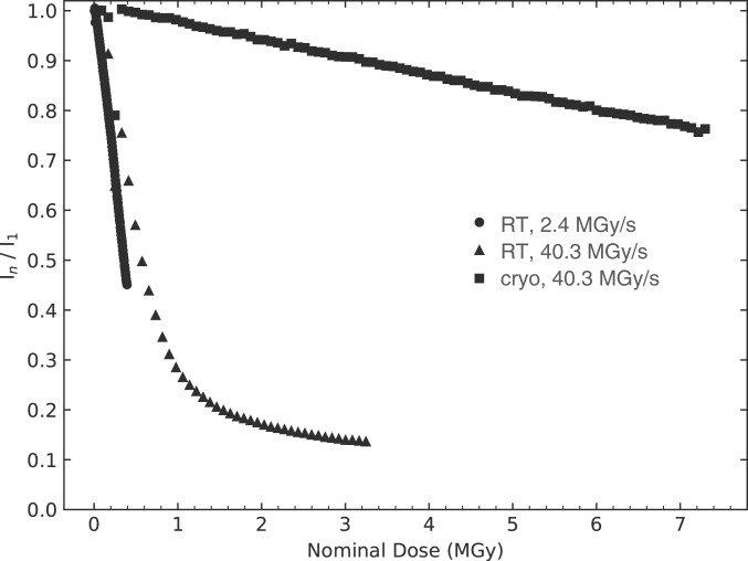
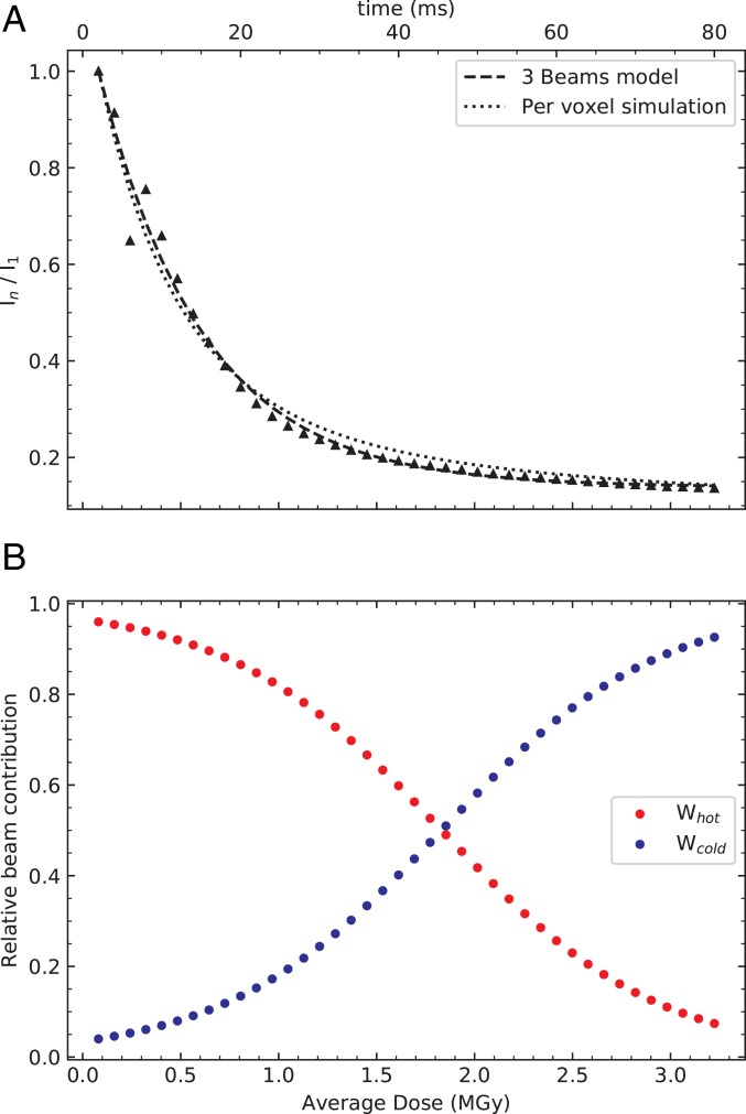
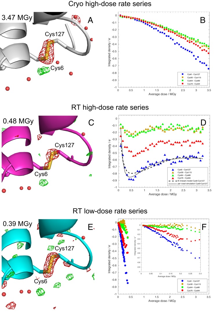
Radiation damage limits the accuracy of macromolecular structures in X-ray crystallography. Cryogenic (cryo-) cooling reduces the global radiation damage rate and, therefore, became the method of choice over the past decades. The recent advent of serial crystallography, which spreads the absorbed energy over many crystals, thereby reducing damage, has rendered room temperature (RT) data collection more practical and also extendable to microcrystals, both enabling and requiring the study of specific and global radiation damage at RT. Here, we performed sequential serial raster-scanning crystallography using a microfocused synchrotron beam that allowed for the collection of two series of 40 and 90 full datasets at 2- and 1.9-Å resolution at a dose rate of 40.3 MGy/s on hen egg white lysozyme (HEWL) crystals at RT and cryotemperature, respectively. The diffraction intensity halved its initial value at average doses (D1/2) of 0.57 and 15.3 MGy at RT and 100 K, respectively. Specific radiation damage at RT was observed at disulfide bonds but not at acidic residues, increasing and then apparently reversing, a peculiar behavior that can be modeled by accounting for differential diffraction intensity decay due to the nonuniform illumination by the X-ray beam. Specific damage to disulfide bonds is evident early on at RT and proceeds at a fivefold higher rate than global damage. The decay modeling suggests it is advisable not to exceed a dose of 0.38 MGy per dataset in static and time-resolved synchrotron crystallography experiments at RT. This rough yardstick might change for proteins other than HEWL and at resolutions other than 2 Å.
Keywords: X-ray radiation damage; room temperature synchrotron data collection; serial crystallography.
Copyright © 2020 the Author(s). Published by PNAS.
Conflict of interest statement
The authors declare no competing interest.
Figures
Similar articles
-
Room-temperature serial crystallography at synchrotron X-ray sources using slowly flowing free-standing high-viscosity microstreams.Acta Crystallogr D Biol Crystallogr. 2015 Feb;71(Pt 2):387-97. doi: 10.1107/S1399004714026327. Epub 2015 Jan 23. Acta Crystallogr D Biol Crystallogr. 2015. PMID: 25664750
-
Evaluation of the data-collection strategy for room-temperature micro-crystallography studied by serial synchrotron rotation crystallography combined with the humid air and glue-coating method.Acta Crystallogr D Struct Biol. 2021 Mar 1;77(Pt 3):300-312. doi: 10.1107/S2059798321001686. Epub 2021 Feb 25. Acta Crystallogr D Struct Biol. 2021. PMID: 33645534 Free PMC article.
-
Radiation damage of protein crystals at cryogenic temperatures between 40 K and 150 K.J Synchrotron Radiat. 2002 Jul 1;9(Pt 4):198-201. doi: 10.1107/s0909049502008579. Epub 2002 Jun 30. J Synchrotron Radiat. 2002. PMID: 12091725
-
Radiation damage to protein specimens from electron beam imaging and diffraction: a mini-review of anti-damage approaches, with special reference to synchrotron X-ray crystallography.J Synchrotron Radiat. 2007 Jan;14(Pt 1):116-27. doi: 10.1107/S0909049506052307. Epub 2006 Dec 15. J Synchrotron Radiat. 2007. PMID: 17211078 Review.
-
Radiation Damage in Macromolecular Crystallography.Methods Mol Biol. 2017;1607:467-489. doi: 10.1007/978-1-4939-7000-1_20. Methods Mol Biol. 2017. PMID: 28573586 Review.
Cited by
-
Room-temperature serial synchrotron crystallography of the human phosphatase PTP1B.Acta Crystallogr F Struct Biol Commun. 2023 Jan 1;79(Pt 1):23-30. doi: 10.1107/S2053230X22011645. Epub 2023 Jan 1. Acta Crystallogr F Struct Biol Commun. 2023. PMID: 36598353 Free PMC article.
-
Probing ligand binding of endothiapepsin by `temperature-resolved' macromolecular crystallography.Acta Crystallogr D Struct Biol. 2022 Aug 1;78(Pt 8):964-974. doi: 10.1107/S205979832200612X. Epub 2022 Jul 27. Acta Crystallogr D Struct Biol. 2022. PMID: 35916221 Free PMC article.
-
High-Resolution Electron Diffraction of Hydrated Protein Crystals at Room Temperature.ACS Nano. 2023 Dec 26;17(24):24802-24813. doi: 10.1021/acsnano.3c05378. Epub 2023 Oct 27. ACS Nano. 2023. PMID: 37890869 Free PMC article.
-
Rapid and efficient room-temperature serial synchrotron crystallography using the CFEL TapeDrive.IUCrJ. 2022 Oct 31;9(Pt 6):778-791. doi: 10.1107/S2052252522010193. eCollection 2022 Nov 1. IUCrJ. 2022. PMID: 36381150 Free PMC article.
-
Variability in X-ray induced effects in [Rh(COD)Cl]2 with changing experimental parameters.Phys Chem Chem Phys. 2022 Nov 30;24(46):28444-28456. doi: 10.1039/d2cp03928a. Phys Chem Chem Phys. 2022. PMID: 36399064 Free PMC article.
References
-
- Garman E. F., Weik M., Radiation damage in macromolecular crystallography. Methods Mol. Biol. 1607, 467–489 (2017). - PubMed
-
- Burmeister W. P., Structural changes in a cryo-cooled protein crystal owing to radiation damage. Acta Crystallogr. D Biol. Crystallogr. 56, 328–341 (2000). - PubMed
-
- Ravelli R. B., McSweeney S. M., The “fingerprint” that X-rays can leave on structures. Structure 8, 315–328 (2000). - PubMed
-
- Adam V., et al. , Structural basis of X-ray-induced transient photobleaching in a photoactivatable green fluorescent protein. J. Am. Chem. Soc. 131, 18063–18065 (2009). - PubMed
Publication types
MeSH terms
Substances
Associated data
- Actions
- Actions
Grants and funding
LinkOut - more resources
Full Text Sources
Other Literature Sources
Miscellaneous
