. 2020 Feb;48(2):300060520903669.
doi: 10.1177/0300060520903669.

Finite element analysis of a new plate for Pauwels type III femoral neck fractures

Affiliations

Finite element analysis of a new plate for Pauwels type III femoral neck fractures

Gang Wang et al. J Int Med Res. 2020 Feb.

Abstract

Background: A new plate for the treatment of Pauwels type III femoral neck fractures was developed, and its biomechanical stability was analyzed by the finite element method.

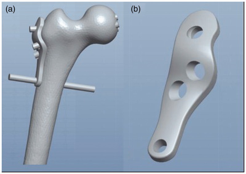
Method: Using 3-matic and UG-NX software, we constructed models of Pauwels type III femoral neck fractures with angles of 50°, 60°, and 70°. Moreover, a new femoral neck plate (NFNP) fixation model and a Pauwels screw fixation model were developed. Under axial loads of 1400 N and 2100 N, von Mises stress (VMS) distribution on the screws, peak VMS, displacement between fracture fragments, and model principal strains in cancellous bone were recorded.

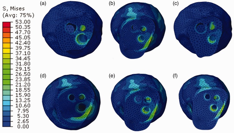
Result: The peak VMS of internal fixation in the two models was mostly located near the fracture line, and the screw closest to the femoral calcar experienced maximum stress. With a Pauwels angle of 50°, 60°, and 70°, the peak VMS values of the new plates were lower than in the Pauwels screw. The displacement of fracture fragments in the NFNP was smaller than in the Pauwels screw, and peak VMS values of cancellous bone in the NFNP were lower than in the Pauwels screw.

Conclusion: The newly developed plate provided excellent biomechanical stability for Pauwels type III femoral neck fractures.

Keywords: Pauwels type III femoral neck fracture; displacement; finite element analysis; new femoral neck plate; peak VMS; von Mises stress.


Figures

Figure 1.
Figure 1.
The plate was designed using 3-matic software. (a) 3D model of the plate and femur. (b) 3D model of the plate.
Figure 2.
Figure 2.
The new plate and screws.
Figure 3.
Figure 3.
Fixation model of the plate and screws. (a) The plate with screws inserted. (b) Orthotopic view of the plate on a femoral model. (c) Lateral view of the femoral model with plate and screws.
Figure 4.
Figure 4.
Bone fracture model, with Pauwels angles of 50°, 60°, and 70°.
Figure 5.
Figure 5.
3D images of two internal fixation methods. (a) The newly developed plate system. (b) Fixation with three cancellous screws.
Figure 6.
Figure 6.
Results of the mesh convergence study. Displacement at the point of load application in the 70° Pauwels cannulated screw (PCS) model as a function of the number of elements.
Figure 7.
Figure 7.
The mesh distribution appearance diagram in the 70° Pauwels cannulated screw (PCS) model.
Figure 8.
Figure 8.
Von Mises stress (VMS) distribution of two internal fixation methods under an axial load of 1400 N. (a, b, c) New femoral neck plate (NFNP) method at Pauwels angles of (a) 50°, (b) 60°, and (c) 70°. (d, e, f) Pauwels cannulated screw (PCS) method at Pauwels angles of (d) 50°, (e) 60°, and (f) 70°.
Figure 9.
Figure 9.
Von Mises stress (VMS) distribution of two internal fixation methods under an axial load of 2100 N. (a, b, c) New femoral neck plate (NFNP) method at Pauwels angles of (a) 50°, (b) 60°, and (c) 70°. (d, e, f) Pauwels cannulated screw (PCS) method at Pauwels angles of (d) 50°, (e) 60°, and (f) 70°.
Figure 10.
Figure 10.
Graphic demonstration of the peak stress for two internal fixation methods at different Pauwels angles under axial loads of 1400 N and 2100 N.
Figure 11.
Figure 11.
Graphic demonstration of the displacement for two internal fixation methods at different Pauwels angles under axial loads of 1400 N and 2100 N.
Figure 12.
Figure 12.
Von Mises stress (VMS) distribution of the proximal femoral neck under an axial load of 1400 N. (a, b, c) New femoral neck plate (NFNP) method at Pauwels angles of (a) 50°, (b) 60°, and (c) 70°. (d, e, f) Pauwels cannulated screw (PCS) method at Pauwels angles of (d) 50°, (e) 60°, and (f) 70°.
Figure 13.
Figure 13.
Von Mises stress (VMS) distribution of the proximal femoral neck under an axial load of 2100 N. (a, b, c) New femoral neck plate (NFNP) method at Pauwels angles of (a) 50°, (b) 60°, and (c) 70°. (d, e, f) Pauwels cannulated screw (PCS) method at Pauwels angles of (d) 50°, (e) 60°, and (f) 70°.
Figure 14.
Figure 14.
Graphic demonstration of the peak stress of the proximal femoral neck on different internal fixation methods under increasing Pauwels angles under axial loads of 1400 N and 2100 N.

References

    1. Liporace F, Gaines R, Collinge Cet al. Results of internal fixation of Pauwels type-3 vertical femoral neck fractures. J Bone Joint Surg Am 2008; 90: 1654–1659. - PubMed
    1. Marsh JL, Slongo TF, Agel Jet al. Fracture and dislocation classification compendium - 2007: Orthopaedic Trauma Association classification, database and outcomes committee. J Orthop Trauma 2007; 21: S1–S133. - PubMed
    1. Kunapuli SC, Schramski MJ, Lee ASet al. Biomechanical analysis of augmented plate fixation for the treatment of vertical shear femoral neck fractures. J Orthop Trauma 2015; 29: 144–150. - PubMed
    1. Huang HK, Su YP, Chen CMet al. Displaced femoral neck fractures in young adults treated with closed reduction and internal fixation. Orthopedics 2010; 33: 873. - PubMed
    1. Haidukewych GJ, Rothwell WS, Jacofsky DJet al. Operative treatment of femoral neck fractures in patients between the ages of fifteen and fifty years. J Bone Joint Surg Am 2004; 86-A: 1711–1716. - PubMed