Review
. 2020 May;412(14):3285-3297.
doi: 10.1007/s00216-020-02411-3. Epub 2020 Feb 14.

Engineering vertically interrogated interferometric sensors for optical label-free biosensing

Affiliations
Review

Engineering vertically interrogated interferometric sensors for optical label-free biosensing

Rafael Casquel et al. Anal Bioanal Chem. 2020 May.

Abstract

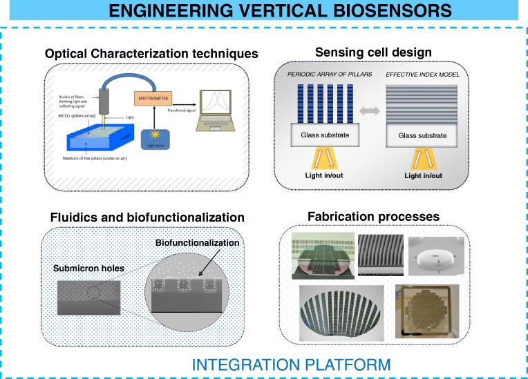
In this work, we review the technology of vertically interrogated optical biosensors from the point of view of engineering. Vertical sensors present several advantages in the fabrication processes and in the light coupling systems, compared with other interferometric sensors. Four different interrelated aspects of the design are identified and described: sensing cell design, optical techniques used in the interrogation, fabrication processes, fluidics, and biofunctionalization of the sensing surface. The designer of a vertical sensor should decide carefully which solution to adopt on each aspect prior to finally integrating all the components in a single platform. Complexity, cost, and reliability of this platform will be determined by the decisions taken on each of the design process. We focus on the research and experience acquired by our group during last years in the field of optical biosensors.

Keywords: Biosensing; Interferometric sensors; Nanofabrication; Optical sensors; Photonic calculations.


Conflict of interest statement

The authors declare that they have no conflict of interest.

Figures

Fig. 1
Fig. 1
Nanometric SU-8 pillars vertically characterized. From [32]. a SEM caption of an array of pillars. b Functionalization of BSA and recognition of anti-BSA on an single pillar. c biorecognition curve
Fig. 2
Fig. 2
Left: Schematic of resonant nanopillars arrays. Optical response of resonant nanopillars. a SEM caption of fabricated R-NPs. b Chip of eight sensing cells. c Fluidic holder. d SEM detail of a pillar. e Dimensions and layers of the pillar. [Reprinted/Adapted] with permission from [43] © The Optical Society. Right: f Biorecognition curve of anti-IgGs from a R-NPs cell. g Reflectivity as a function of wavelength for a R-NPs cell, saturated with IgGs and after anti-IgGs recognition. [Reprinted/Adapted] with permission from [44] © The Optical Society
Fig. 3
Fig. 3
Areas of interest of vertical Interferometric biosensors to be integrated on a single platform
Fig. 4
Fig. 4
a Schematic of the layout of characterized Su-8 nanopillars. b Equivalent thin film model used for analytical calculations. From [49]
Fig. 5
Fig. 5
Equivalent 1-D model for resonant nanopillars
Fig. 6
Fig. 6
Schematic of reflectometry at profile level. The optical setup focuses the laser beam on the surface of a sensing cell with a sub-micrometric spot. The system obtains reflectivity for a variety of angles, for pure polarizations s and p, and for a combination of polarization states. [Reprinted/Adapted] with permission from [59] © The Optical Society
Fig. 7
Fig. 7
a Top view of a lattice of SU-8 pillars with a pith of 10 μm, and a diameter in the order of 5 μm, with the laser source of RPL focused on the centre of a pillar. b SEM caption of a single pillar with 1.15 μm in height and 5.28 μm in width
Fig. 8
Fig. 8
PoC readout system based on IROP. a Block diagram of the functionality of the PoC: IRef generates the interferometric reference and ISig produces the interferometric signal as a result of the biological accumulation. fTRANS is the operation between both signals and delivers IROP (%). b Optical layout of the LED and photodiode. c Hardware components. d A set of KITs based on FPIs as biosensors. e Biosensing response as a function of the angle of incidence for a biofilm thickness of 20 nm. From [64]
Fig. 9
Fig. 9
a Sensing surface biofunctionalized with A-protein and anti-MMP9. b Biorecognition of MMP9. From [71]
Fig. 10
Fig. 10
a Silanization of R-NPs. b Comparison of the mode shift from the silanization and anti-IgGs recognition for eight arrays of a single chip. [Reprinted/Adapted] with permission from [44] © The Optical Society
Fig. 11
Fig. 11
a Scheme of pillars immersed in water, b scheme of pillars in dry conditions, and c layout of the measurement system. From [73]
Fig. 12
Fig. 12
a Comparison of anti-IgG detection with wet and dry conditions. b Reflectivity of the sensing cell in dry conditions for IgG and anti-IgG saturation. c Reflectivity of the sensing cell immersed in water, for IgG and anti-IgG saturation. From [73]

References

    1. Liedberg B, Nylander C, Lunström I. Surface plasmon resonance for gas detection and biosensing. Sensors Actuators. 1983;4:299–304.
    1. Homola J, Yee SS, Gauglitz G. Surface plasmon resonance sensors: review. Sensors Actuators B Chem. 1999;54:3–15.
    1. Homola J. Surface plasmon resonance sensors for detection of chemical and biological species. Chem Rev. 2008;108:462–493. - PubMed
    1. Passaro V, Dell’Olio F, Casamassima B, De Leonardis F. Guided-wave optical biosensors. Sensors. 2007;7:508–536.
    1. Ksendzov A, Lin Y. Integrated optics ring-resonator sensors for protein detection. Opt Lett. 2005;30:3344. - PubMed

LinkOut - more resources