Review
. 2020 Feb 14;25(4):833.
doi: 10.3390/molecules25040833.

Microfluidics in Haemostasis: A Review

Affiliations
Review

Microfluidics in Haemostasis: A Review

Heta Jigar Panchal et al. Molecules. .

Abstract

Haemostatic disorders are both complex and costly in relation to both their treatment and subsequent management. As leading causes of mortality worldwide, there is an ever-increasing drive to improve the diagnosis and prevention of haemostatic disorders. The field of microfluidic and Lab on a Chip (LOC) technologies is rapidly advancing and the important role of miniaturised diagnostics is becoming more evident in the healthcare system, with particular importance in near patient testing (NPT) and point of care (POC) settings. Microfluidic technologies present innovative solutions to diagnostic and clinical challenges which have the knock-on effect of improving health care and quality of life. In this review, both advanced microfluidic devices (R&D) and commercially available devices for the diagnosis and monitoring of haemostasis-related disorders and antithrombotic therapies, respectively, are discussed. Innovative design specifications, fabrication techniques, and modes of detection in addition to the materials used in developing micro-channels are reviewed in the context of application to the field of haemostasis.

Keywords: Coagulation; LOC; MEMS; POC; haemostasis; microfluidics.


Conflict of interest statement

The authors declare no conflict of interest.

Figures

Figure 1
Figure 1
Microfluidic disc with two sample reservoirs and one mixing channel. After injecting samples into the reservoir in an uneven manner and applying centrifugal force, the sample with more volume starts flowing faster, and the uniform mixing is achieved in the long mixing channel. Taken with permission from [30].
Figure 2
Figure 2
Microfluidic device design with six chambers to carry out three prothrombin time (PT) requiring one reagent inlet and three activated partial thromboplastin time (aPTT) assays that require inlets for reagents I and II. Taken with permission from [23].
Figure 3
Figure 3
Schematic representation of droplet-based microfluidic device with a long channel for continuous analysis of thrombin generation in real-time. Taken with permission from [33].
Figure 4
Figure 4
A biomimetic microfluidic device with angular bends designed to represent different shear rates at the diseased regions of the vascular system including a diagram of the device showing the stenosed, pre-stenosed and post-stenosed regions of the microchannel, a schematic of the haemostasis monitor and device and a photograph of three devices in a PDMS mold on a glass substrate. Taken with permission from [39].
Figure 5
Figure 5
(A) Microfluidic device with 13 channels mounted on a glass slide patterned with a collagen strip [40]. (B) Schematic representation of a microfluidic device comprised of 8 parallel test chambers. Taken with permission from [12].
Figure 6
Figure 6
(A) High-throughput microfluidic chip with seven parallel wells for measuring blood coagulation time [42]. (B) MEMS-based microfluidic device [43]. (C) Schematic representation of a paper-based microfluidic chip. Taken with permission from [44].
Figure 7
Figure 7
Electrical model representing three major blood components responsible for blood impedance, Rp – plasma resistance, Ri – Red blood cell interior resistance and Cm – Cell membrane capacitance. Taken with permission from [42].
Figure 8
Figure 8
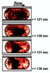
Bright-field microscopic image analysis of a single plug representing the formation of the clot through a dark spot with respect to time. Taken with permission from [32].
Figure 9
Figure 9
(A) Charged-coupled device (CCD) optical detection of the laser beam transmitted to the microfluidic device developed for a platelet aggregation study [74]. (B) Experimental set-up showing a digital camera mounted over the paper-based microfluidic device to capture images every 15s during the test [75]. (C) Smartphone based detection system of a paper-on-polydimethylsiloxane (PDMS) device using LED emission light. Taken with permission from [76].
Figure 10
Figure 10
(A) Placement of components in a microfluidic device working on the principle of resonant frequency [80]. (B) Working set-up of the microfluidic cartridge. Taken with permission from [43].
Figure 11
Figure 11
Schematic representation of the photolithographic fabrication technique. (A) A photoresist is spin-coated onto a silicon substrate. (B) The substrate with the spin-coated layer of photoresist is exposed to UV light through a high-resolution mask. (C) After baking and chemical development, the non-cross-linked material is removed, resulting in either a positive or a negative mold. Taken with permission from [111].
Figure 12
Figure 12
(A) Illustration of the fabrication process of a microfluidic chip using a glass wafer for electrode deposition and a silicon wafer for PDMS microchannel formation [22]. (B) Fabrication process for an electrochemical impedance-based blood coagulation device using photolithography. Taken with permission from [42].
Figure 13
Figure 13
A high throughput eight chamber microfluidic chip composed of polymethylmethacrylate (PMMA), polycarbonate PC and pressure sensitive adhesive (PSA) and manufactured using laser micromachining The top layer (a), middle layer (b), and bottom layer (c) are assembled into a composite chip in (d). Taken with permission from [120].
Figure 14
Figure 14
(A) Solid wax-printed microfluidic chip for separation of plasma from whole blood. (B) Schematic representation of a working µPAD. Taken with permission from [128].
Figure 15
Figure 15
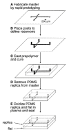
Schematic representation of micro-channel fabrication using soft lithography. (A) A high-resolution transparency containing the design of the channels, created in a CAD program, was used as the mask in photolithography to produce a positive relief of photoresist on a silicon wafer. The scale bar gives an indication of the thickness and width of photoresist. (B) Glass posts were placed on the wafer to define reservoirs for analytes and buffers. (C) A prepolymer of PDMS was then cast onto the silicon wafer and cured at 65 °C for 1 h. (D) The polymer replica of the master containing a negative relief of channels was peeled away from the silicon wafer, and the glass posts were removed. (E) The PDMS replica and a flat slab of PDMS were oxidized in a plasma discharge for 1 min. Plasma oxidation had two effects. First, when two oxidized PDMS surfaces were brought into conformal contact, an irreversible seal formed between them. This seal defined the channels as four walls of oxidized PDMS. Second, silanol (SiOH) groups introduced onto the surface of the polymer ionize in neutral or basic aqueous solutions and support EOF in the channels. Taken with permission from [131].
Figure 16
Figure 16
Experimental set-up: Collagen/kaolin patterned to a glass slide with a thickness of 250 µm. The microfluidic device with 8 inlets was then bonded to the glass slide. Taken with permission from [135].

Similar articles

Cited by

References

    1. Runyon M.K., Johnson-Kerner B.L., Kastrup C.J., Van Ha T.G., Ismagilov R.F. Propagation of Blood Clotting in the Complex Biochemical Network of Hemostasis Is Described by a Simple Mechanism. J. Am. Chem. Soc. 2007;129:7014–7015. doi: 10.1021/ja072602p. - DOI - PubMed
    1. Wolberg A.S., Aleman M.M., Leidarman K., Machlus K.R. Procoagulant Activity in Hemostasis and Thrombosis: Virchow’s Triad Revisited. Anesth. Analg. 2012;114:275–285. doi: 10.1213/ANE.0b013e31823a088c. - DOI - PMC - PubMed
    1. Zhang C., Neelamegham S. Application of microfluidic devices in studies of thrombosis and hemostasis. Platelets. 2017;28:434–440. doi: 10.1080/09537104.2017.1319047. - DOI - PMC - PubMed
    1. Convery N., Gadegaard N. 30 Years of Microfluidics. Micro Nano Eng. 2019;2:76–91. doi: 10.1016/j.mne.2019.01.003. - DOI
    1. Chiu D.T., de Mello A.J., Di Carlo D., Doyle P.S., Hansen C., Maceiczyk R.M., Wootton R.C.R. Small but Perfectly Formed? Successes, Challenges, and Opportunities for Microfluidics in the Chemical and Biological Sciences. Chem. 2017;2:201–223. doi: 10.1016/j.chempr.2017.01.009. - DOI