

Characterisation and Modelling of Ultrashort Laser-Driven Electromagnetic Pulses
- PMID: 32080268
- PMCID: PMC7033110
- DOI: 10.1038/s41598-020-59882-8
Characterisation and Modelling of Ultrashort Laser-Driven Electromagnetic Pulses
Abstract
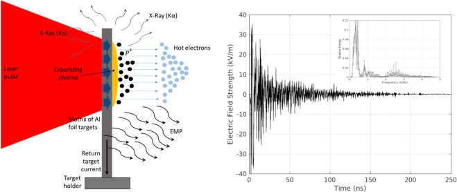
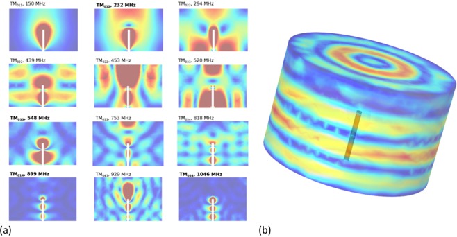
Recent advances on laser technology have enabled the generation of ultrashort (fs) high power (PW) laser systems. For such large scale laser facilities there is an imperative demand for high repetition rate operation in symbiosis with beamlines or end-stations. In such extreme conditions the generation of electromagnetic pulses (EMP) during high intense laser target interaction experiments can tip the scale for the good outcome of the campaign. The EMP effects are several including interference with diagnostic devices and actuators as well as damage of electrical components. The EMP issue is quite known in the picosecond (ps) pulse laser experiments but no systematic study on EMP issues at multi-Joule fs-class lasers has been conducted thus far. In this paper we report the first experimental campaign for EMP-measurements performed at the 200 TW laser system (VEGA 2) at CLPU laser center. EMP pulse energy has been measured as a function of the laser intensity and energy together with other relevant quantities such as (i) the charge of the laser-driven protons and their maximum energy, as well as (ii) the X-ray Kα emission coming from electron interaction inside the target. Analysis of experimental results demonstrate (and confirm) a direct correlation between the measured EMP pulse energy and the laser parameters such as laser intensity and laser energy in the ultrashort pulse duration regime. Numerical FEM (Finite Element Method) simulations of the EMP generated by the target holder system have been performed and the simulations results are shown to be in good agreement with the experimental ones.
Conflict of interest statement
The authors declare no competing interests.
Figures


References
-
- Hamster, H., Sullivan, A., Gordon, S., White, W. & Falcone, R. Subpicosecond, electromagnetic pulses from intense laser-plasma interaction. Physical Review Letters 71 (1993). - PubMed
-
- Flacco A, et al. Persistence of magnetic field driven by relativistic electrons in a plasma. Nature Physics. 2015;11:409–413. doi: 10.1038/nphys3303. - DOI
-
- Kahaly S, et al. Polarimetric detection of laser induced ultrashort magnetic pulses in overdense plasma. Physics of Plasmas. 2009;16:043114. doi: 10.1063/1.3118586. - DOI
-
- Cheng, C.-C., Wright, E. M. & Moloney, J. V. Generation of electromagnetic pulses from plasma channels induced by femtosecond light strings. Physical Review Letters 87 (2001). - PubMed
Grants and funding
- FIS2016-81056-R/Cabildo Insular de La Palma
- FIS2016-81056-R/Cabildo Insular de La Palma
- FIS2016-81056-R/Cabildo Insular de La Palma
- FIS2016-81056-R/Cabildo Insular de La Palma
- CLP087U16/Consejería de Educación, Junta de Castilla y León (Consejería de Educación de la Junta de Castilla y León)
- CLP087U16/Consejería de Educación, Junta de Castilla y León (Consejería de Educación de la Junta de Castilla y León)
- CLP087U16/Consejería de Educación, Junta de Castilla y León (Consejería de Educación de la Junta de Castilla y León)
- CLP087U16/Consejería de Salud, Junta de Andalucía (Ministry of Health, Andalusian Regional Government)
LinkOut - more resources
Full Text Sources
