Review
. 2020 Feb 18;7(1):17.
doi: 10.3390/bioengineering7010017.

Recapitulating the Vasculature Using Organ-On-Chip Technology

Affiliations
Review

Recapitulating the Vasculature Using Organ-On-Chip Technology

Andreas M A O Pollet et al. Bioengineering (Basel). .

Abstract

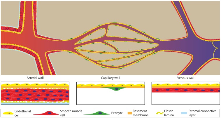
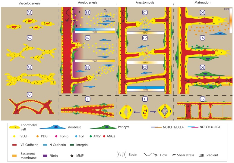
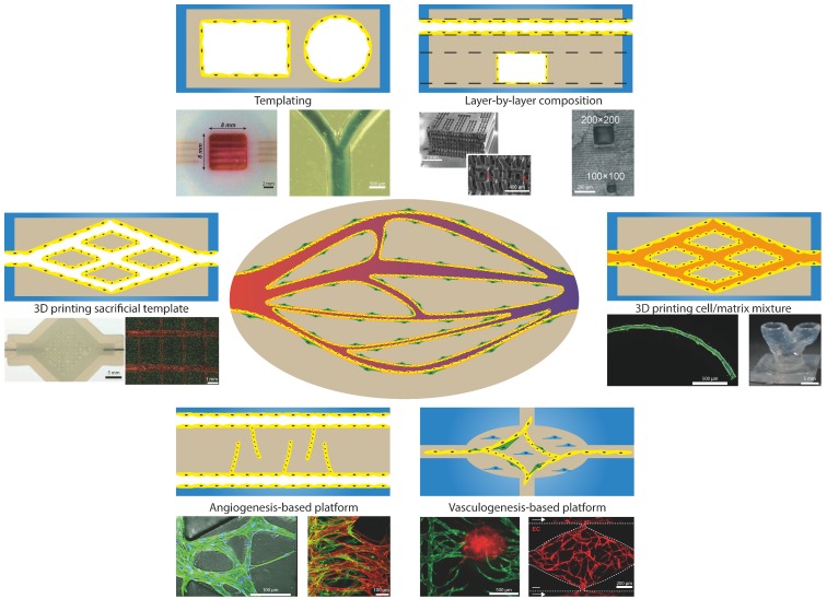
The development of Vasculature-on-Chip has progressed rapidly over the last decade and recently, a wealth of fabrication possibilities has emerged that can be used for engineering vessels on a chip. All these fabrication methods have their own advantages and disadvantages but, more importantly, the capability of recapitulating the in vivo vasculature differs greatly between them. The first part of this review discusses the biological background of the in vivo vasculature and all the associated processes. We then evaluate the biological relevance of different fabrication methods proposed for Vasculature-on-Chip, we indicate their possibilities and limitations, and we assess which fabrication methods are capable of recapitulating the intrinsic complexity of the vasculature. This review illustrates the complexity involved in developing in vitro vasculature and provides an overview of fabrication methods for Vasculature-on-Chip in relation to the biological relevance of such methods.

Keywords: angiogenesis; microfabrication; microfluidics; organ-on-chip; vasculature; vasculogenesis.


Conflict of interest statement

The funders had no role in the design of the study; in the collection, analyses, or interpretation of the data; in the writing of the manuscript, or in the decision to publish the results.

Figures

Figure 1
Figure 1
Schematic overview of the vasculature tree. Left: the arteries have large diameter vessels with a thick layer of smooth muscle cells. They transport blood from the heart and narrow down to transit to the capillary bed (middle) which bifurcates into smaller and closely spaced vessels to increase the exchange of oxygen and nutrients with the tissue and to decrease the required diffusion distance within the tissue. The capillary vessels consist mostly of only endothelial cells with a thin basement membrane supported by pericytes. The vessels bundle back together to form the venous part of the vasculature (right), which are again thicker and have a layer of smooth muscle cells, however not as abundant as in the arterial part. The venous system also has valves inside the lumen to prevent backflow and pumping action by the muscles around it, and it finally leads the blood back to the heart. Image inspired by [5,6].
Figure 2
Figure 2
Overview of processes involving remodelling of the vasculature. Vasculogenesis is the process of forming de novo vasculature. A1 The process starts with endothelial precursor cells scattered throughout the tissue. A2 These precursor cells form clumps or islands of endothelial cells, A3 which grow and form a primitive network structure. A4 Upon full connection, the network opens up for perfusion, forming a primitive plexus. Angiogenesis is the process of forming new vasculature from an existing vessel. B1 If oxygen concentration decreases, cells start to express VEGF via HIF-1α signalling which creates a gradient. When the vessel wall senses the increase in VEGF, the VE-Cadherin connections between endothelial cells loosen up, resulting in leakage of fibrin from the blood plasma into the surrounding matrix. Together with the expression and activation of MMPs, the matrix is remodelled to form a temporary matrix suitable for migration and sprouting. Sprouting endothelial cells release ANG2 upon which pericytes detach from the endothelial cells by disconnecting the N-Cadherin junctions. B2 The initial VEGF gradient results in the selection of tip cells, which use integrins to migrate through the matrix and express DLL4 to inhibit neighbouring cells, adopting a tip cell phenotype via Notch1. Via this Notch signalling cascade, a single tip cell is maintained followed by stalk cells expressing Jagged1. B3 Sprouts follow a gradient of VEGF, Semaphorins and Ephrins. Besides chemotactic migration, sprouts also migrate into the direction of interstitial flow, acting as a mechanical guidance. Due to Notch signalling within the sprout, following stalk cells stay connected to the tip cells, forming a continuous train of cells which opens up. E Besides sprouting, intussusception (or splitting angiogenesis) is also a method for forming new blood vessels. This process involves opposing endothelial cells making contact through the lumen of the blood vessel. After this, the vessel wall is remodelled until it is fully developed, resulting in a tissue pillar through the blood vessel. If this process is further promoted, a complete vessel can be split in two smaller vessels or bifurcations can be progressed into the vessel. C1 Anastomosis is guided via gradients, resulting in chemotaxis. Besides this gradient, the tip cells pull on the matrix to be able to migrate forward. This pulling results in fibres being strained between the two tip cells, forming a strain gradient that forms a guide for the tip cells to migrate towards each other and anastomose. C2 Upon contact between two tip cells, the filopodia form a connection via VE-Cadherin, stabilising the connection. This process is guided by myeloid cells expressing Notch1. C3 When the lumen of both sprouts are connected, the oxygen and nutrient levels increase, again reducing the expression of VEGF. F The formation of lumens can happen by two possible mechanisms. Left: Vacuoles are released from the endothelial cells towards the basal side of the forming lumen. This opens up a central cavity that can be perfused upon connection. Right: Glycoproteins that are negatively charged are present on the membrane at the basal side. Based on charge repulsion, the two membranes move away from each other, forming a lumen. Maturation: D1 during angiogenesis, sprouting endothelial cells express PDGF, which recruits pericytes to stabilise the vessel wall. The expression of PDGF forms a chemotactic gradient for fibroblasts to migrate towards the sprout and adopt a pericytes phenotype. D2 When fibroblasts connect to the sprouts, they adopt a pericyte phenotype. Based on this switch, N-Cadherin is expressed, connecting the pericytes to the endothelial cells and stabilising the vessel wall. Expression of ANG1 by the pericytes results in clustering at the cell–cell junctions to increase vessel tightness and results in endothelial cell quiescence. D3 Top: Expression of TGF-promotes ECM production and proliferation by pericytes as well as inducing a pericyte phenotype. Bottom: Fully stable and mature vessel wall. Pericytes adopt a phalanx state around the endothelial lumen. Low concentrations of VEGF, ANG1, and FGF are required for survival and stabilisation. Notch-3-JAG-1 signalling is required for survival and so are shear stresses, resulting from flow, acting on the endothelial cells. Endothelial cells are tightly connected together via VE-Cadherin and to pericytes via N-Cadherin; both endothelial cells and pericytes connect to the ECM via integrins. G Regression of vessels also occurs when perfusion is no longer required. The process starts by a reduced flow through the vessel resulting in a lower shear stress level. This low shear stress acts as a cue for endothelial cells to retract from the vessel and to close off the lumen. After complete retraction of the vessel, only the basement membrane is left, which will be remodelled over time to form a normal tissue ECM. Image inspired by [9,10,11].
Figure 3
Figure 3
Different methodologies for recreating the Vasculature-on-Chip exist. These different methods can be divided roughly into the following groups. Templating: is based on having a template structure which can be removed after adding a matrix material with or without cells. This normally is done using a needle or fibre for creating circular channels or soft lithography for mostly square channels. Examples taken from: left [41] (scale bar 2 mm), right [47] (scale bar 500 µm). Layer-by-layer composition: Based on lithography processes, multiple layers with specific designs can be stacked upon each other, forming a complex 3D network. The main challenge is being able to properly align and bond multiple layers to achieve one connected network. Examples taken from: left [49] (scale bar top: 1 mm, bottom: 400 µm), right [51] (scale bar 200 µm). 3D printing sacrificial template: This method is the next level beyond templating; more complex structures can be 3D printed and the desired matrix material can be casted around these structures. After solidification of the matrix, the printed structure is removed by dissolving, melting, or chemical breakdown, leaving an open structure. Examples taken from: left [57] (scale bar 5 mm), right [59] (scale bar 1 mm). 3D printing cell/matrix mixture: By changing from a template to directly printing cells and matrix, more design freedom is obtained. However, the process becomes more complex and the printed networks are less accurate. Examples taken from: left [67] (scale bar 500 µm), right [64] (scale bar 5 mm). Angiogenesis-based platforms: This method employs angiogenesis from an existing vessel or an endothelial layer into a matrix, either by a chemotactic gradient or by activating angiogenesis in the endothelial layer. This method is able to recapitulate the sprouting and angiogenesis process to a large extent, however forming networks that resemble an in vivo vascular network remains challenging. Examples taken from: left [72] (scale bar 100 µm), right [73] (scale bar 100 µm). Vasculogenesis-based platforms: Here the biological process is stimulated to form the networks. By giving the right initial conditions (Endothelial cells, fibroblasts, and Fibrin in most cases, as well as flow), the mixture of cells and matrix is promoted to form vascular networks similar to in vivo ones. The control over this process is worse than in other methods but it can be steered by understanding the biological processes at play. Examples taken from: left [79] (scale bar 500 µm), right [87] (scale bar 200 µm). Images based on [1,41,47,49,51,57,59,64,67,72,73,79,87].

References

    1. Hasan A., Paul A., Vrana N.E., Zhao X., Memic A., Hwang Y.-S., Dokmeci M.R., Khademhosseini A. Microfluidic techniques for development of 3D vascularized tissue. Biomaterials. 2014;35:7308–7325. doi: 10.1016/j.biomaterials.2014.04.091. - DOI - PMC - PubMed
    1. Bogorad M.I., DeStefano J., Karlsson J., Wong A.D., Gerecht S., Searson P.C. Review: In vitro microvessel models. Lab Chip. 2015;15:4242–4255. doi: 10.1039/C5LC00832H. - DOI - PMC - PubMed
    1. Lee S., Ko J., Park D., Lee S.R., Chung M., Lee Y., Jeon N.L. Microfluidic-based vascularized microphysiological systems. Lab Chip. 2018;18:2686–2709. doi: 10.1039/C8LC00285A. - DOI - PubMed
    1. Marieb E.N. Human Anatomy & Physiology. Pearson Benjamin Cummings; San Francisco, CA, USA: 2004. The cardiovascular system: Blood vessels; pp. 711–770. Chapter 19.
    1. Gotlieb A.I., Liu A. Chapter 10. Blood vessels. In: Rubin R., Strayer D.S., Rubin E., editors. Rubin’s Pathology: Clinicopathologic Foundations of Medicine. Wolters Kluwer Health/Lippincott Williams & Wilkins; Philadelphia, PA, USA: 2012. pp. 435–478.

LinkOut - more resources