. 2020 Feb 24;11(1):1014.
doi: 10.1038/s41467-020-14679-1.

Geology of the InSight landing site on Mars

Affiliations

Geology of the InSight landing site on Mars

M Golombek et al. Nat Commun. .

Abstract

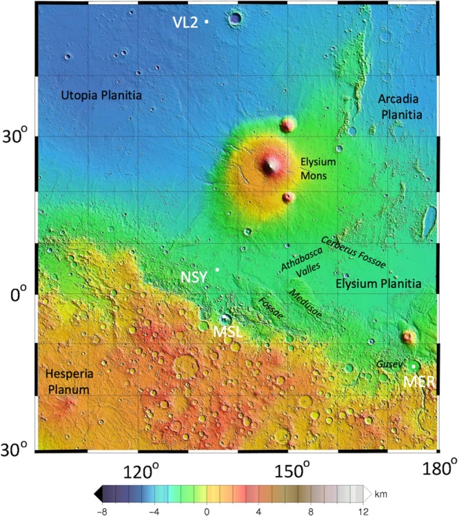
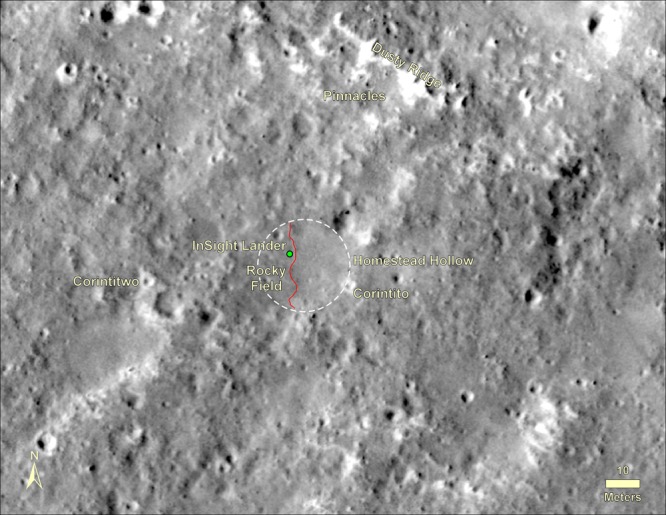
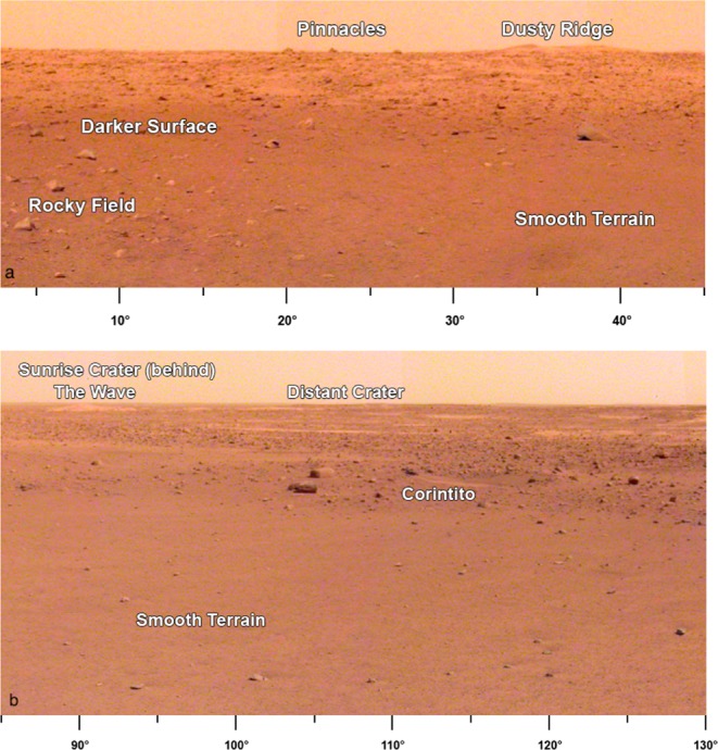
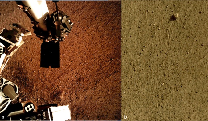
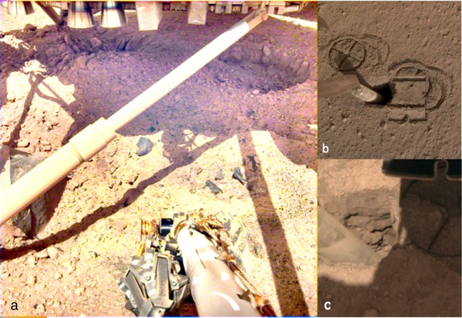
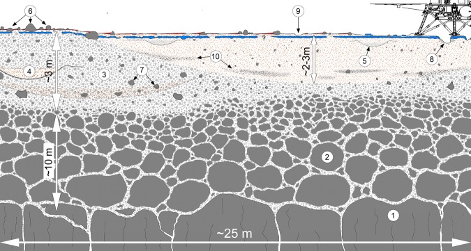
The Interior Exploration using Seismic Investigations, Geodesy and Heat Transport (InSight) spacecraft landed successfully on Mars and imaged the surface to characterize the surficial geology. Here we report on the geology and subsurface structure of the landing site to aid in situ geophysical investigations. InSight landed in a degraded impact crater in Elysium Planitia on a smooth sandy, granule- and pebble-rich surface with few rocks. Superposed impact craters are common and eolian bedforms are sparse. During landing, pulsed retrorockets modified the surface to reveal a near surface stratigraphy of surficial dust, over thin unconsolidated sand, underlain by a variable thickness duricrust, with poorly sorted, unconsolidated sand with rocks beneath. Impact, eolian, and mass wasting processes have dominantly modified the surface. Surface observations are consistent with expectations made from remote sensing data prior to landing indicating a surface composed of an impact-fragmented regolith overlying basaltic lava flows.


Conflict of interest statement

The authors declare no competing interests.

Figures

Fig. 1
Fig. 1. Topographic map of the region around the InSight landing site.
The map shows InSight (NSY) and major physiographic features as well as the landing sites of the Viking Lander 2 (VL2), Mars Science Laboratory (MSL) Curiosity in Gale crater, and the Mars Exploration Rover (MER) Spirit in Gusev crater. InSight landed near the dichotomy boundary between the heavily cratered highlands to the south and the northern lowlands. Volcanic flows from Elysium Mons flowed to the south and very young lavas from Cerberus Fossae flowed down Athabasca Valles to 150 km to the east of the lander. The map is a portion of the MOLA shaded relief topographic map of Mars with elevations with respect to the geoid.
Fig. 2
Fig. 2. InSight landing ellipses and spacecraft locations.
Image shows the landing ellipse (E9, dark blue, 130 km × 27 km), with trajectory correction maneuver 5 (TCM5) course adjusted target (green dot), the last orbit determination solution and ellipse (LaRC green, 77.4 km × 23.2 km), the extrapolated inertial measurement unit (IMU) surface location, the RISE estimate from Sol 1 (4.49751° ± 0.00471°N, 135.6178693° ± 0.000337°E, hidden behind the lander dot, red), and HiRISE-based location from December 6th, 2018. Background image mosaic is from the daytime Thermal Emission Imaging System (THEMIS) infrared global mosaic at 100 m/pixel. The dominant surface is smooth Early Amazonian-Hesperian plains deformed by north-trending wrinkle ridges (suggesting subsurface basalt flows) with large impact craters,. Craters larger than around 40 m but smaller than around 2 km are dark (indicating colder daytime temperatures with higher thermal inertia), rocky ejecta craters. These craters excavate strong coherent rock (basalt) from depths of 4–200 m depth, with a fractured regolith on top and weaker sediments beneath,,.
Fig. 3
Fig. 3. HiRISE image of InSight.
a Image acquired on December 6, 2018 showing a regional view of the location of the InSight lander, parachute and backshell, and heatshield. Also shown are close ups of the heat shield (b) lander (c) and parachute and backshell (d) in color. Note the 20 m radius dark spot around the lander, with the slightly brighter interior. The gradational extension of the dark spot to the southeast is along the prevailing wind direction from the northwest estimated from orbit and measured by InSight early in the mission. Note smaller dark spots associated with the backshell and heatshield, and the relatively fresh Sunrise crater 400 m to the east of the lander. Note circular impact craters in a wide variety of degradational states. Portion of HiRISE image ESP_057939_1845and ESP_058005_1845 at ~25 cm/pixel.
Fig. 4
Fig. 4. HiRISE image of region in view from the lander.
Image shows the lander (green dot), and rocks, craters and bedforms observed in surface images. Note the relatively fresh, rocky ejecta crater Sunrise (~100 m diameter) about 400 m to the east and nearby bedforms observed from the lander (The Wave) that are typically near the rim or inside craters. Panoramas show terrain about 50 m to the north to the rim of a degraded crater (~100 m diameter) where bedforms (Dusty Ridge) and rocks (The Pinnacles) can be seen. Also note Corinto secondary craters (five yellow arrows and Corintito) with their characteristic bright ejecta. Portion of HiRISE image ESP_036761_1845.
Fig. 5
Fig. 5. HiRISE image of Homestead hollow.
Image shows the location of the InSight lander (green dot) in Homestead hollow (white dashed circle) and surface features identified from the ground. Note smooth terrain to the east of the lander and slightly rougher and rockier terrain (Rocky field) to the west (red line is the contact) and throughout much of the image. Bedforms (Dusty ridge) and three rocks (The Pinnacles) are about 50 m away to the north-northeast (see Fig. 4). Note two Corinto secondary craters that can be seen from the lander: Corintito (20 m to the southeast) and Corintitwo (40 m to the west). Portion of HiRISE image ESP_036761_1845.
Fig. 6
Fig. 6. Portion of panoramas around the lander.
a Panorama is the area to the north-northeast of the lander (azimuths below image). Note darker surface where dust has been removed within 20 m of the lander, rockier surface to the west (Rocky field), and smooth terrain to the east. Note The Pinnacles rocks and Dusty Ridge, which is an eolian bedforms on the southern edge of a degraded impact crater, located about 50 m north of the lander. b Portion of panorama to the east-southeast (azimuths below image) of the lander showing smooth terrain to the edge of Homestead hollow and rougher and rockier terrain beyond. Note fresh Corinto secondary crater (Corintito) on the edge of the hollow, circular soil filled depressions (hollows) in the distance, and eolian bedforms (The Wave) and Sunrise crater rim on the horizon about 400 m away. The rim of a larger (460 m diameter), relatively fresh crater (Distant crater) to the east-southeast is ~2.4 km away.
Fig. 7
Fig. 7. IDC images of the soil surface near the lander.
a Image shows the radial striations in the soil. High resolution digital elevation models show millimeters of relief between the ridges and grooves. Some elongate hills have pebbles at the lander facing end suggesting they protected the tails of material behind. The radial pattern and tails behind pebbles suggests dispersal of mostly unconsolidated sand away from the lander by the retrorockets. The lack of evidence for more significant scour around larger rocks suggests that only millimeters of sand has been removed around the lander (which would have minimal impact on clast and rock counts). The dark rectangle in the center of the image is the scoop at the end of the arm, which is 7.1 cm wide. The horseshoe shaped notch in the front blade of the scoop can be seen in the scoop indentation in Fig. 8b. b Image shows surface divots that record the displacement of the ~5 cm diameter pebble named Rolling Stones Rock. Approximately 10 divots show the pebble skipped and rolled about 1 m across the surface. The divots indicate the soils are fine grained and unconsolidated.
Fig. 8
Fig. 8. Images of shallow subsurface structure.
a Image shows pits under the lander with spacecraft strut, retrorockets, excavated pits (~10 cm deep, ~50 cm across), dark gray, very fine-grained rocks (basalt) and duricrust. Note steep pit walls of soil and clasts in a finer-grained matrix, indicating cemented duricrust and clods and fragments of the duricrust that litter the pits and surface. Pulsed retrorockets on the Phoenix lander eroded 5–18 cm of material beneath the lander. A contrast stretch has been applied to this image to accentuate details in the shadowed areas. b Image of mole hole and surface after interactions with the HP3 SSA feet and scoop. Circular cross patterns are imprints of the HP3 SSA feet in the soil. Smooth, reflective rectangular surface is where the flat base of the scoop (7.1 cm wide) was pressed against the soil, causing a ~5 mm indentation. Note the horseshoe shaped outline of the front blade of the scoop imprint (Fig. 7a). Horizontal troughs near the top and bottom of the scoop imprint are where the front blade of the scoop penetrated into the soil. c) Image of hole created by the HP3 mole showing resistant layers in the wall of the pit. These layers have steep edges and overhangs indicating cohesion in the soil. Small rocks appear cemented in a fine-grained matrix, similar to the pits beneath the lander. Mole is angled 2.7 cm diameter cylinder (~15°), to the left.
Fig. 9
Fig. 9. Interpretive cross section of the shallow subsurface beneath the InSight lander.
Most of the surficial bright, reddish dust (red, shown behind some rocks) has been dispersed around the lander (above 8). Rockier areas beyond ~20 m have more surface dust (6). The dust, which settled out of the atmosphere, is likely microns thick. About 1 cm of unconsolidated sand indicated by the radial surface striations and surface divots (9) underlies the dust. Observed in the pits beneath the lander (8) and in the mole hole is a duricrust of cemented sand, pebbles and rocks that is 5–10 cm thick (shown in blue), but could vary in thickness. Beneath the duricrust are overlapping craters (4, 5), rocks (7), and lens of ejecta from other craters (10). The relatively fine-grained impact generated regolith (3) is around 3 m thick beneath the lander and likely grades with depth into coarse, blocky ejecta (2) that overlies fractured basalt flows (1). Observations from the lander described in the text support the top 10 cm of the cross section. The bottom 13 m of the cross section are derived from estimates of the thickness of the relatively fine-grained regolith from rocky and non-rocky ejecta craters,, and the original depth of the Homestead hollow crater. Note the varying vertical scale.
Fig. 10
Fig. 10. Rock size-frequency distributions.
a Cumulative fractional area and b cumulative number per m2 versus diameter of rocks near the InSight lander as well as those measured at the Spirit (Spirit CMS for Columbia Memorial Station) and Phoenix (PHX) landing sites. Also shown are exponential model size-frequency distributions for rock abundances (k) of 1%, 2%, 3%, 5% and 10%. Note curves in b are not exponentials and approach a straight line at small diameter (note that fractional area is dependent on the diameter squared, whereas cumulative number is not), but are matches to the exponential models based on cumulative fractional area in (a). Surface rock counts are: near and far RAD spots (NSYT NFF RAD and NSYT FF RAD, respectively), the workspace (NSYT WS), the area to the northwest (NSYT NW), and the area to the south with the largest rocks (NSYT LRG). Spirit CMS from Golombek et al., Phoenix intermediate area (PHX INT) from Heet et al. and Phoenix largest rocks (PHX LRG) from Golombek et al.. Measurement uncertainty as stated earlier is between 1–4 mm, which would have no appreciable effect on the plots.

References

    1. Banerdt, W. B. et al. Early results from the InSight mission: surface environment and global seismic activity. Nat. Geosci. 10.1038/s41561-020-0544-y (2020).
    1. Golombek M, et al. Selection of the InSight landing site. Space Sci. Rev. 2017;211:5–95.
    1. Golombek M, et al. Geology and physical properties investigations by the InSight Lander. Space Sci. Rev. 2018;214:84.
    1. Tanaka, K. L., et al. Geologic Map of Mars, 1:20,000,000, USGS Scientific Investigations Map 3292 (2014).
    1. Smrekar SE, et al. Pre-mission InSights on the interior of Mars. Space Sci. Rev. 2018;215:3.

Publication types