

Effect of Laser Pulse Overlap and Scanning Line Overlap on Femtosecond Laser-Structured Ti6Al4V Surfaces
- PMID: 32098103
- PMCID: PMC7079643
- DOI: 10.3390/ma13040969
Effect of Laser Pulse Overlap and Scanning Line Overlap on Femtosecond Laser-Structured Ti6Al4V Surfaces
Abstract
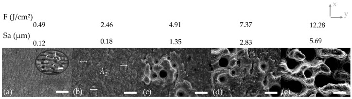
Surface structuring is a key factor for the tailoring of proper cell attachment and the improvement of the bone-implant interface anchorage. Femtosecond laser machining is especially suited to the structuring of implants due to the possibility of creating surfaces with a wide variety of nano- and microstructures. To achieve a desired surface topography, different laser structuring parameters can be adjusted. The scanning strategy, or rather the laser pulse overlap and scanning line overlap, affect the surface topography in an essential way, which is demonstrated in this study. Ti6Al4V samples were structured using a 300 fs laser source with a wavelength of 1030 nm. Laser pulse overlap and scanning line overlap were varied between 40% and 90% over a wide range of fluences (F from 0.49 to 12.28 J/cm²), respectively. Four different main types of surface structures were obtained depending on the applied laser parameters: femtosecond laser-induced periodic surface structures (FLIPSS), micrometric ripples (MR), micro-craters, and pillared microstructures. It could also be demonstrated that the exceedance of the strong ablation threshold of Ti6Al4V strongly depends on the scanning strategy. The formation of microstructures can be achieved at lower levels of laser pulse overlap compared to the corresponding value of scanning line overlap due to higher heat accumulation in the irradiated area during laser machining.
Keywords: Ti6Al4V; ablation threshold; femtosecond laser; laser pulse overlap; scanning line overlap; ultrashort laser pulse.
Conflict of interest statement
The authors declare no conflict of interest. The funders had no role in the design of the study; in the collection, analyses, or interpretation of data; in the writing of the manuscript; or in the decision to publish the results.
Figures


Similar articles
-
Heat Accumulation-Induced Surface Structures at High Degrees of Laser Pulse Overlap on Ti6Al4V Surfaces by Femtosecond Laser Texturing.Materials (Basel). 2023 Mar 21;16(6):2498. doi: 10.3390/ma16062498. Materials (Basel). 2023. PMID: 36984383 Free PMC article.
-
Femtosecond laser-induced surface nanostructures for tribological applications.In: König K, Ostendorf A, editors. Optically Induced Nanostructures: Biomedical and Technical Applications. Berlin: De Gruyter; 2015 Jun 23. Chapter 7. In: König K, Ostendorf A, editors. Optically Induced Nanostructures: Biomedical and Technical Applications. Berlin: De Gruyter; 2015 Jun 23. Chapter 7. PMID: 26491777 Free Books & Documents. Review.
-
Creating superhydrophobic and antibacterial surfaces on gold by femtosecond laser pulses.Appl Surf Sci. 2020 Mar 15;506:144952. doi: 10.1016/j.apsusc.2019.144952. Appl Surf Sci. 2020. PMID: 32184533 Free PMC article.
-
Biocompatibility of micro/nano structures on the surface of Ti6Al4V and Ti-based bulk metallic glasses induced by femtosecond laser.Biomater Adv. 2022 Aug;139:212998. doi: 10.1016/j.bioadv.2022.212998. Epub 2022 Jun 25. Biomater Adv. 2022. PMID: 35882146
-
Micro/Nano Periodic Surface Structures and Performance of Stainless Steel Machined Using Femtosecond Lasers.Micromachines (Basel). 2022 Jun 20;13(6):976. doi: 10.3390/mi13060976. Micromachines (Basel). 2022. PMID: 35744590 Free PMC article. Review.
Cited by
-
Evaluation of Bronze Electrode in Electrical Discharge Coating Process for Copper Coating.Micromachines (Basel). 2023 Jan 4;14(1):136. doi: 10.3390/mi14010136. Micromachines (Basel). 2023. PMID: 36677197 Free PMC article.
-
Influence of Femtosecond Laser Modification on Biomechanical and Biofunctional Behavior of Porous Titanium Substrates.Materials (Basel). 2022 Apr 19;15(9):2969. doi: 10.3390/ma15092969. Materials (Basel). 2022. PMID: 35591307 Free PMC article.
-
A New Method for Modeling the Cyclic Structure of the Surface Microrelief of Titanium Alloy Ti6Al4V After Processing with Femtosecond Pulses.Materials (Basel). 2020 Nov 5;13(21):4983. doi: 10.3390/ma13214983. Materials (Basel). 2020. PMID: 33167467 Free PMC article.
-
Scanning Strategies in Laser Surface Texturing: A Review.Micromachines (Basel). 2023 Jun 12;14(6):1241. doi: 10.3390/mi14061241. Micromachines (Basel). 2023. PMID: 37374826 Free PMC article. Review.
-
Scanning Algorithm Optimization for Achieving Low-Roughness Surfaces Using Ultrashort Laser Pulses: A Comparative Study.Materials (Basel). 2023 Mar 30;16(7):2788. doi: 10.3390/ma16072788. Materials (Basel). 2023. PMID: 37049082 Free PMC article.
References
-
- Brunette D.M., Tengvall P., Textor M., Thomsen P. Titanium in Medicine. Material Science, Surface Science, Engineering, Biological Responses and Medical Applications. Springer; Berlin/Heidelberg, Germany: 2001.
-
- Sykaras N., Iacopino A.M., Marker V.A., Triplett R.G., Woody R.D. Implant materials, designs, and surface topographies: Their effect on osseointegration. A literature review. Int. J. Oral Maxillofac. Implant. 2000;15:675–690. - PubMed
Grants and funding
LinkOut - more resources
Full Text Sources
