. 2020 Jan;67(1):328-334.
doi: 10.1109/ted.2019.2953658. Epub 2019 Dec 10.

Second Harmonic 527-GHz Gyrotron for DNP-NMR: Design and Experimental Results

Affiliations

Second Harmonic 527-GHz Gyrotron for DNP-NMR: Design and Experimental Results

Sudheer K Jawla et al. IEEE Trans Electron Devices. 2020 Jan.

Abstract

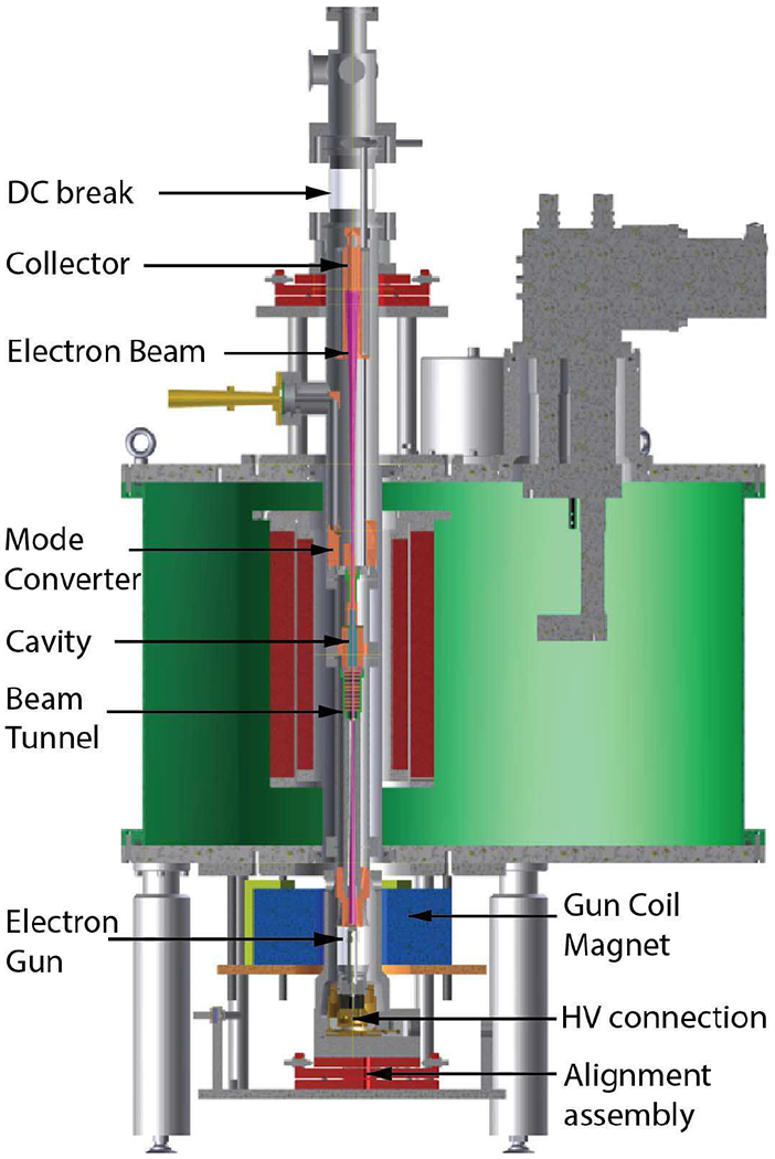
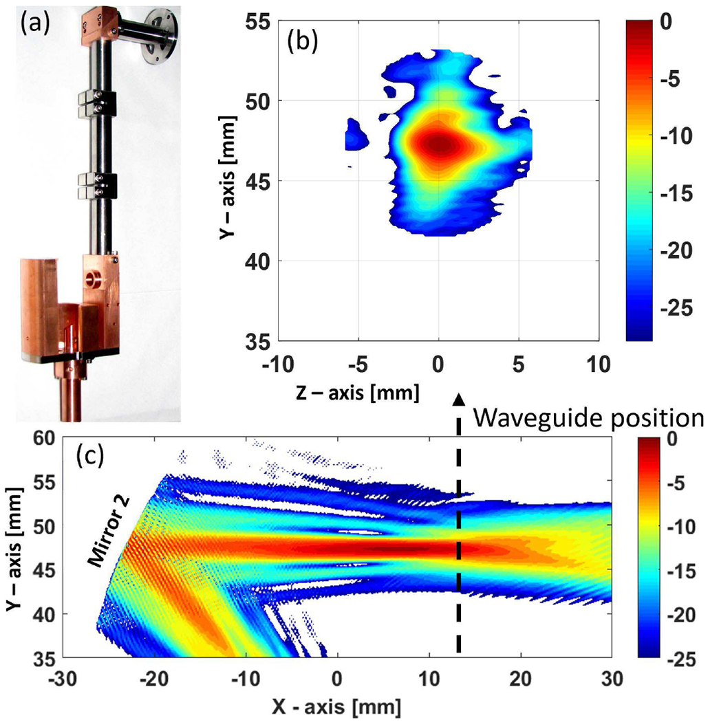
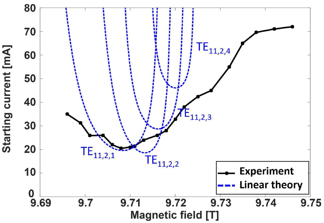
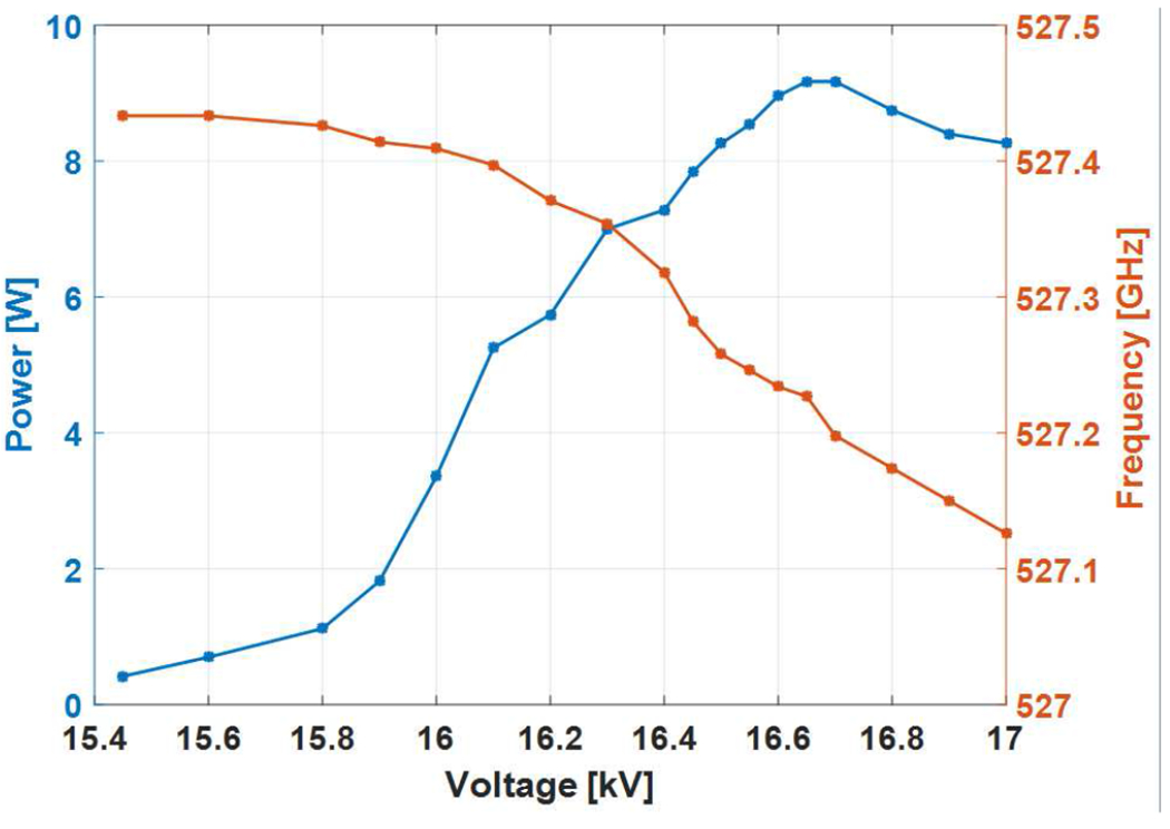
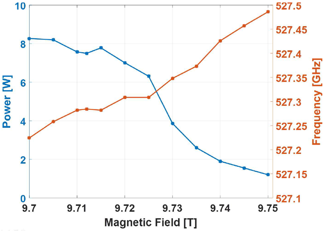
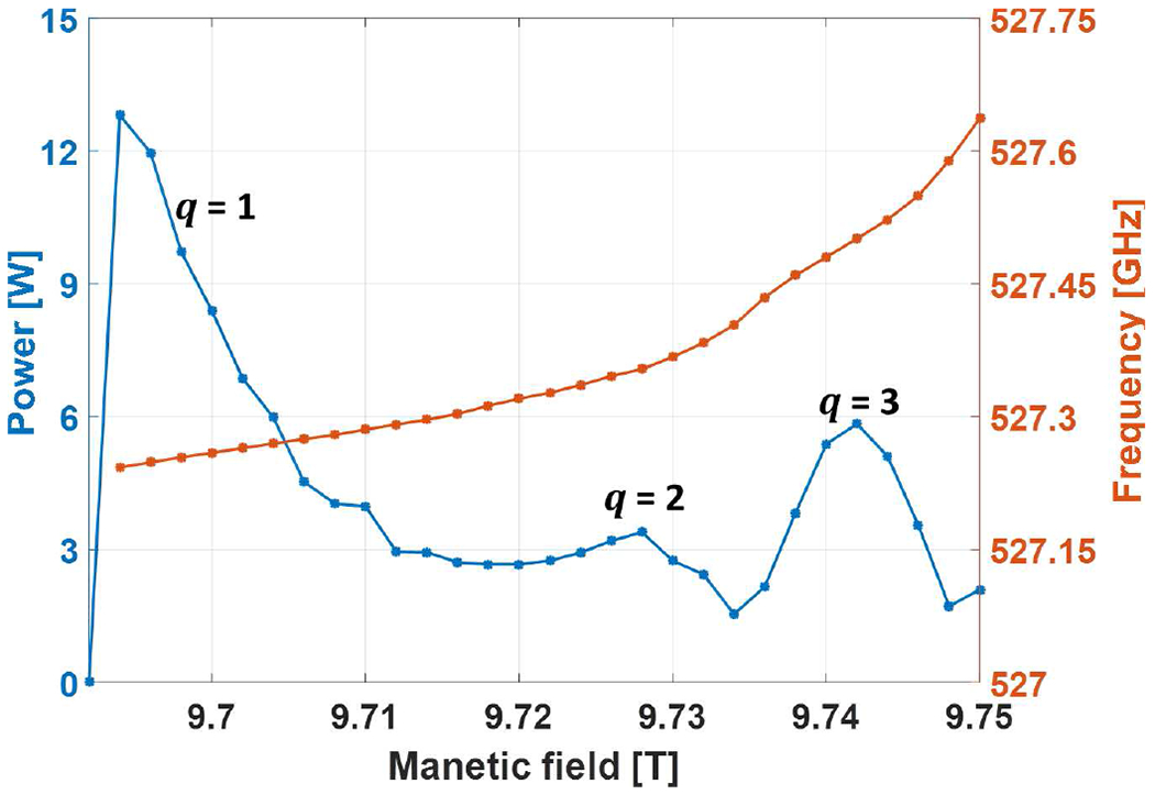
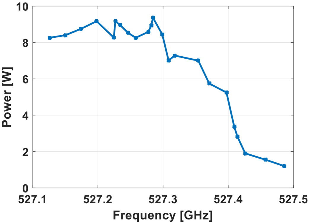
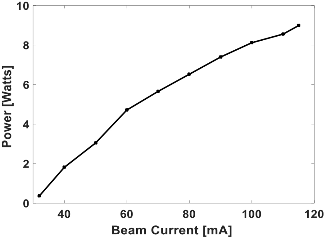
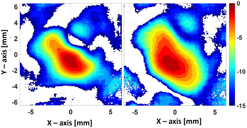
We report the design and experimental demonstration of a frequency tunable terahertz gyrotron at 527 GHz built for an 800 MHz Dynamic Nuclear Polarization enhanced Nuclear Magnetic Resonance (DNP-NMR) spectrometer. The gyrotron is designed at the second harmonic (ω = 2ω c) of the electron cyclotron frequency. It produces up to 9.3 W continuous microwave (CW) power at 527.2 GHz frequency using a diode type electron gun operating at V = 16.65 kV, Ib = 110 mA in a TE11,2,1 mode, corresponding to an efficiency of ~0.5%. The gyrotron is tunable within ~ 0.4 GHz by combining voltage and magnetic field tuning. The gyrotron has an internal mode converter that produces a Gaussian-like beam that couples to the HE11 mode of an internal 12 mm i.d. corrugated waveguide periscope assembly leading up to the output window. An external corrugated waveguide transmission line system is built including a corrugated taper from 12 mm to 16 mm i.d. waveguide followed by 3 m of the 16 mm i.d. waveguide The microwave beam profile is measured using a pyroelectric camera showing ~ 84% HE11 mode content.

Keywords: Corrugated waveguide; Dynamic Nuclear Polarization; Gaussian beam; Terahertz; electron beam; frequency tunable gyrotron.


Figures

Fig. 1.
Fig. 1.
The schematic of the 527 GHz gyrotron in a 10 T SCM (shown in green) is shown. Different components of the tube assembly are labeled. The gyrotron tube is mounted on two assemblies at the top and bottom for alignment along the magnetic field axis.
Fig. 2.
Fig. 2.
Calculated perpendicular to parallel velocity ratio, α, and perpendicular velocity spread, Δv w.r.t. the operating voltage for the diode type electron gun.
Fig. 3.
Fig. 3.
The cavity profile showing 25 mm long resonator section and up tapers. The electric field profile of TE11,2,1 mode is also shown calculated using the self-consistent multimode code MAGY [47].
Fig. 4.
Fig. 4.
Start oscillation current of the operating mode, TE11,2,1, and the neighboring modes w.r.t. the operating magnetic field. Also shown in the center is the electric field profile of the operating mode TE11,2 in a resonator cavity of radius rc = 1.593 mm and the circle representing the electron beam of radius re = 0.97 mm.
Fig. 5.
Fig. 5.
(a) Fabricated mode converter assembly, (b) Intensity profile of the Gaussian beam calculated using Surf3D in a transverse plane before coupling into the corrugated waveguide. (c) Intensity profile for the radiated field after the 1st mirror and in a cut plane showing the position of 2nd mirror and the corrugated waveguide aperture.
Fig. 6.
Fig. 6.
Photograph of the 527 GHz gyrotron tube under test. A 10 T cryo-free superconducting magnet (green color) is seen in the picture along with the gyrotron tube and a small magnet coil, at the bottom of the main magnet, for fine tuning the electron beam parameters. A 16 mm i.d. corrugated waveguide transmission line made of brass is also seen in the picture.
Fig. 7.
Fig. 7.
The measured (solid black line with dots) and calculated (dashed blue lines) start oscillation current of the operating mode TE11,2,q, q = 1,2,3,4 for different magnetic field values. A minimum start current of ~ 21 mA is observed. The calculated start current assumed cold cavity electric field profile in the linear theory for cavity radius of rc = 1.593 and operating voltage of V = 16.7 kV, α = 1.8 and Δv = 3% with the gun coil magnetic field of ~ −37 mT.
Fig. 8.
Fig. 8.
The measured output power and frequency with respect to the operating voltage at the magnetic field of 9.708 T and 110 mA of electron beam current. The gun coil magnet is operated up to ~ −35 mT to maximize the output power.
Fig. 9.
Fig. 9.
The measured output power and frequency with respect to the operating magnetic field and fixed voltage of 16.7 kV and 90 mA of electron beam current. The gun coil magnet is operated up to ~ −35 mT to maximize the output power.
Fig. 10.
Fig. 10.
The simulated output power and frequency with respect to the operating magnetic field at 16.7 kV voltage and 110 mA of electron beam current, α = 1.85 and Δv/v = 5%. The cavity radius used in the calculations is the measured radius of 1.593 mm.
Fig. 11.
Fig. 11.
The measured output power as a function of output frequency for varying magnetic field from 9.69 T to 9.75 T and voltage varying from 15.5 to 17 kV at a beam current of 110 mA.
Fig. 12.
Fig. 12.
The measured output power with respect to the beam current at magnetic field of 9.71 T and 16.7 kV voltage.
Fig. 13.
Fig. 13.
The measured intensity profile at 20 mm (left) and 38 mm (right) from the waveguide aperture after a 3 m long waveguide section using a pyroelectric camera.

References

    1. Abragam A, Goldman M, “Principles of dynamic nuclear polarization”, Reports on Progress in Physics, 41 (3), 395, 1978.
    1. Goldman M, Spin temperature and nuclear magnetic resonance in solids, Oxford University Press: London, 1970.
    1. Griffiths JM, Lakshmi KV, Bennett AE, Raap J, Vanderwielen CM, Lugtenburg J, Herzfeld J, Griffin RG, “Dipolar correlation NMR-spectroscopy of a membrane protein”, J. Am. Chem. Soc, 116, 10178–10181, 1994.
    1. Castellani F, van Rossum B, Diehl A, Schubert M, Rehbein K, Oschkinat H, “Structure of a protein determined by solid-state magic-angle-spinning NMR spectroscopy”, Nature, 420, 98–102, 2002. - PubMed
    1. Maly T, Debelouchina GT, Bajaj VS, Hu KN, Joo CG, Mak-Jurkauskas ML, Sirigiri JR, Wel PC, Herzfeld J, Temkin RJ, Griffin RG, “Dynamic Nuclear Polarization at High Magnetic Fields”, J. Chem. Phys, 128, 052211, 2008. - PMC - PubMed

LinkOut - more resources