. 2020 Jan 22;9(2):e247-e262.
doi: 10.1016/j.eats.2019.10.005. eCollection 2020 Feb.

Anterior Cruciate Ligament Reconstruction Using a Ribbon-Like Graft With a C-Shaped Tibial Bone Tunnel

Affiliations

Anterior Cruciate Ligament Reconstruction Using a Ribbon-Like Graft With a C-Shaped Tibial Bone Tunnel

Christian Fink et al. Arthrosc Tech. .

Abstract

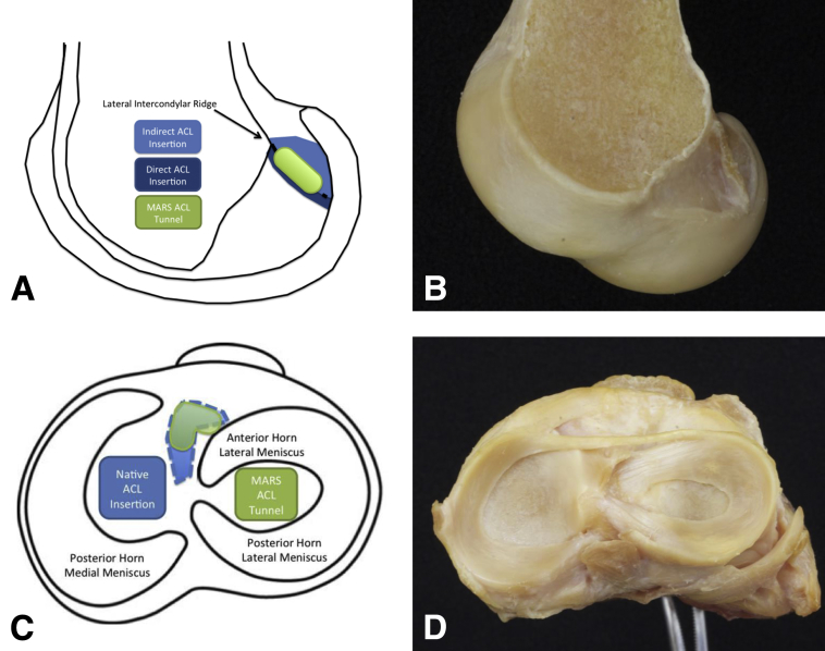
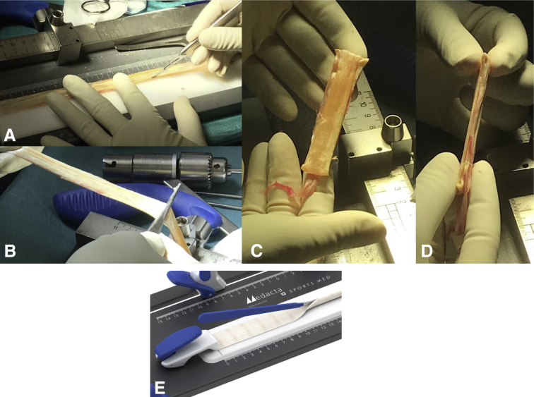
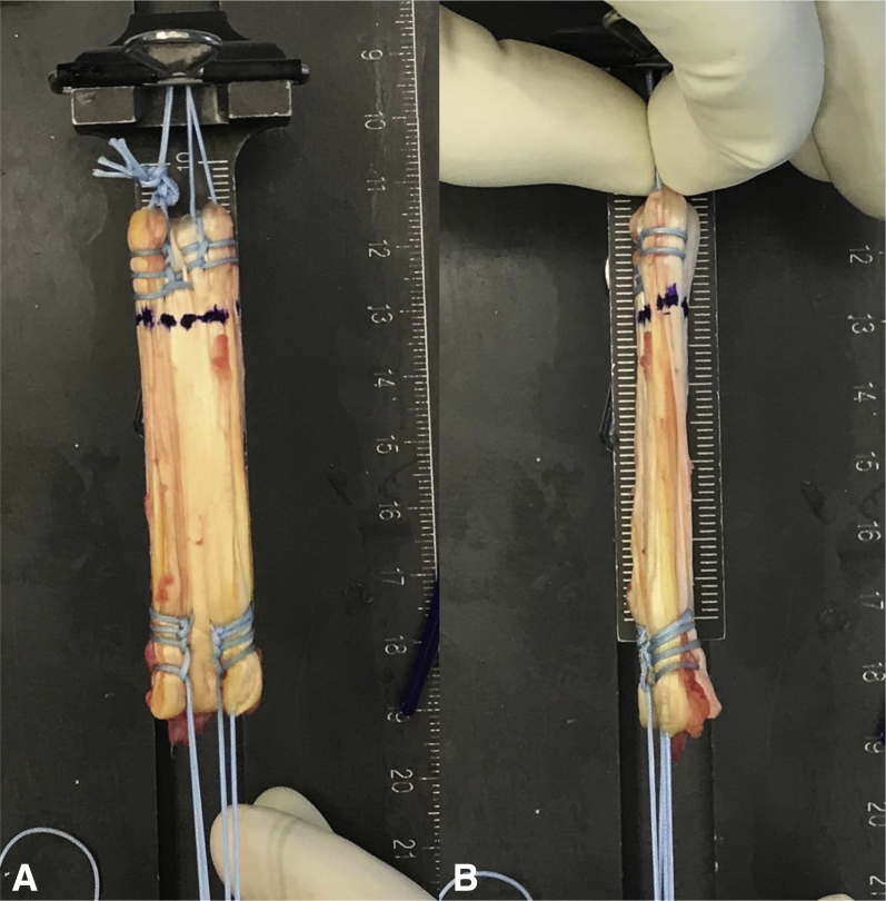
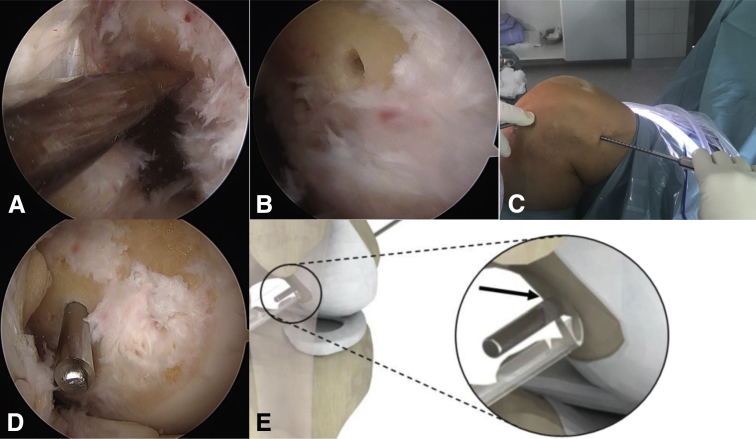
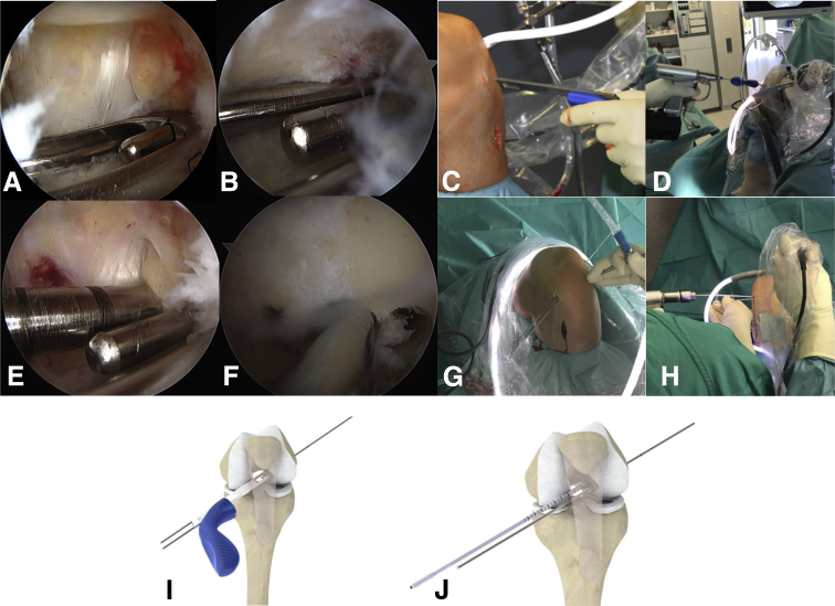
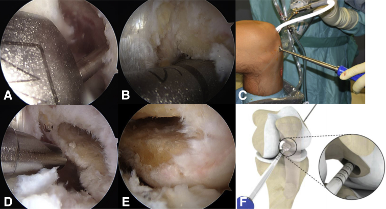
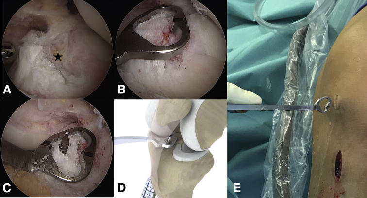
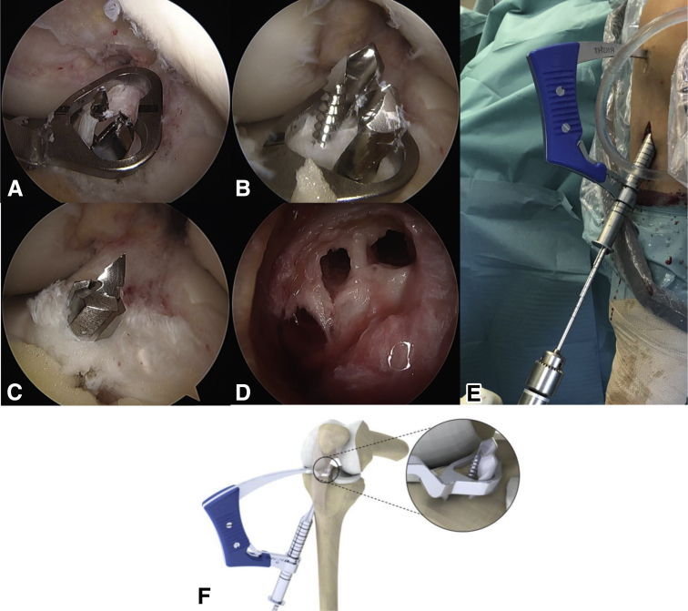
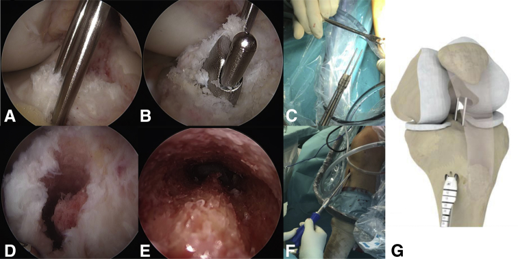
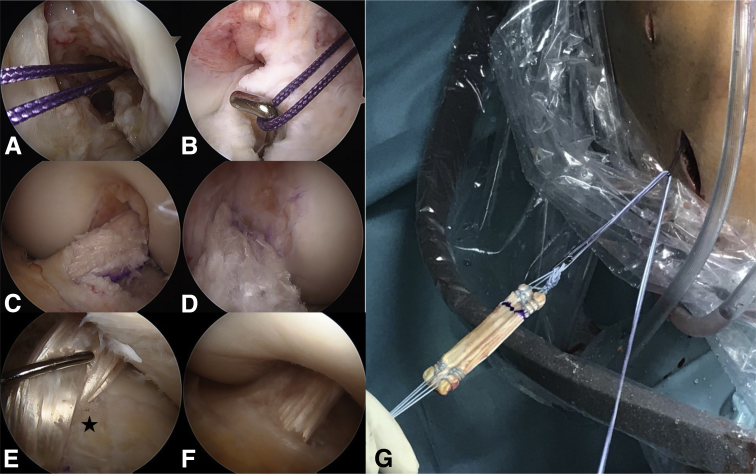
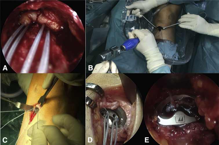
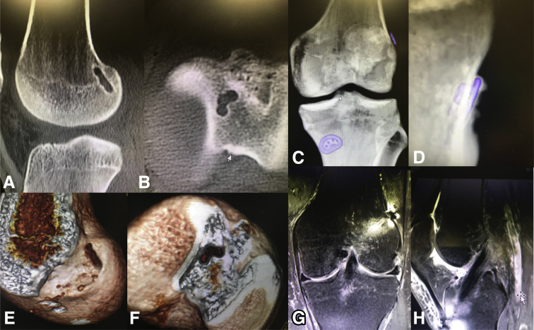
According to recent anatomic studies, the anterior cruciate ligament (ACL) appears to be a flat, "ribbon-like" structure, with a thin, oval-shaped insertion on the femur and a C-shaped tibial insertion. According to this anatomy, we describe an ACL-reconstruction technique that aims to approximate this natural anatomy. The basic principle of this technique is not to use conventional round tunnels but create tunnel shapes that resemble more closely the original ACL insertion sites. Using either a rectangular quadriceps tendon graft or a "flat" hamstring graft may not only provide a biomechanical advantage with increased rotational stability but also improve bone-tendon healing due to increased bone-tendon contact and decreased diffusion length. Creating a C-shaped tibial tunnel also avoids laceration of the anterior horn of the lateral meniscus, which is frequently harmed during conventional tibial tunnel drilling.


Figures

Fig 1
Fig 1
Anatomy of the ACL insertion sites. Smigielski et al. describe the femoral insertion site as crescent-shaped, extending from the intercondylar ridge to the posterior articular margin of the lateral condyle, shown in schematic (A) and in a right cadaveric lateral femoral condyle viewed from medially, with the medial condyle removed (B). The native ACL insertion consists of 2 components: the direct type (dark blue), where fibers entered the bone almost at a right angle and the fanlike indirect fibers (light blue) extending to the articular margin. The location of a rectangular tunnel for reconstruction (green) is shown according to these landmarks. The tibial insertion is described as being C-shaped, from along the lateral edge of the medial tibial spine to the anterior aspect of the anterior root of the lateral meniscus, accommodating within its concavity the insertion of the lateral meniscus. This relation is shown in a schematic drawing of a right tibial plateau viewed from above (C) with the native ACL insertion (light blue) and the C-shaped tunnel (green). (D) Illustration of the corresponding view of a right cadaveric tibial plateau with the native ACL resected 1 cm above its insertion site to demonstrate its relationship to the anterior root of the lateral meniscus. (ACL, anterior cruciate ligament.)
Fig 2
Fig 2
QT graft harvesting. (A) The scar of a QT ACL 3 months postoperatively and is an example for the incision of harvesting the QT. (B).Left knee intraoperatively in 90° of flexion with subcutaneous dissection already done and a Langenbeck retractor inserted to expose the surface of the QT. After exposure of the tendon, a double knife (Medacta) with the adequate width (small, medium, large) is inserted, shown in (C), starting slightly lateral to the midpoint of the superior patellar border, to a minimum depth of 70 mm (judged using calibrations on the instrument handle) and extending 20 mm distally over the patella. Graft thickness is determined with a 4.5-mm tendon separator (Medacta), which undercuts the QT as shown in (D). The separator is inserted to the same length as the parallel-bladed double knife (min. 70 mm) as determined by calibrations on the instrument handle. In (E), proximal tendon division and retrieval are shown in a schematic knee. Both are accomplished using the tendon cutter/grasper (Medacta). A firm compression of the handle divides the tendon proximally subcutaneously. Keeping the tendon cutter closed around the tendon and retrieving it takes the proximal tendon end with it. (ACL, anterior cruciate ligament; QT, quadriceps tendon.)
Fig 3
Fig 3
Final quadriceps tendon graft. (A) The graft with the suture sling for folding the periosteum flap still in place and the proximally already reinforced graft with Krackow-stitches on the lateral edges and a spiral seam in the center. (B) The narrow part of the flat graft. The suturing technique for the distal graft end is Krackow-stitches on both sides, which can be seen in (C) with the PSP already in place. (PSP, Pull Suture Plate.)
Fig 4
Fig 4
Reinforcement of the graft. For easier, the graft is first folded freely on the preparation board for the second time it should be folded over a suture sling attached to the board that is removed afterwards and the free ends are kept in place using a goiter grasping forceps (A). First, the free ends are prepared using an interlocking suturing technique with two size 2 nonabsorbable sutures (FiberWire; Arthrex). (B) Interlocking mechanism in a quadrupled semiT graft.
Fig 5
Fig 5
Converting a round tendon to a flat graft. The tendon is fixed on a preparation board and any fatty or muscular tissue is already removed. The round tendon part of the semiT then is dissected by knife to half of its diameter ([A], with a semiT graft; [E], schematic drawing) and subsequently smoothed into flat shape by blunt raspatorium at minimum pressure (B). As Domnick et al. showed, this does not affect the structural properties of the tissue. As in usual ACL reconstructions using a semiT, the tendon is folded twice after the flattening, however, still keeping its flat shape. We aim for a length of 6 to 7 cm. (C) View on the wide part of the quadrupled graft; and (D) on the narrow part. (ACL, anterior cruciate ligament.)
Fig 6
Fig 6
Final SemiT graft. Krackow-stitches are placed on the outer edges of the proximal graft end. They should be done on the outer 3 mm of the graft and the sutures should go back in the mid part of the graft using a simple spiral seam (A). These sutures are used for suspensory fixation of the graft. The flat appearance is demonstrated on the wide (A) and the narrow (B) part.
Fig 7
Fig 7
Femoral tunnel placement. (A) Arthroscopic view of the medial wall of a lateral femoral condyle of a left knee from a lateral standard portal. The midpoint of the femoral origin of the ACL is marked with a microfracturing instrument. Thereafter, the position can be checked through a medial portal view (B). If the position looks adequate, the 2.4-mm guidewire marked for length measurement is inserted and drilled through until the mark is close to the lateral notch wall (D, arthroscopic view from the medial portal; E, schematic view). Finally, a small incision is made in the skin at the exit point of the guidewire for insertion of the indirect measuring instrument (C, intraoperative view of a left knee from lateral). (ACL, anterior cruciate ligament.)
Fig 8
Fig 8
Aiming for a flat femoral tunnel. (C) The insertion of the femoral guide primarily in line with the incision and in (D) (intraoperative view on a left knee from anterolateral), (I) (schematic drawing) oriented anatomically. (A) Arthroscopic view of the medial wall of the lateral femoral condyle with the first guidewire, described in the previous picture, and the femoral guide already in place from a lateral standard portal. The initial guidewire is inserted in the central hole of the guide and it is then oriented in line of the anatomic ACL insertion. Two other guidewires are drilled through the additional lateral holes in the femoral guide. They don't need to be drilled through the lateral cortex but about 30 mm (I). The femoral aimer is removed (B, arthroscopic view from a lateral standard portal; G, intraoperative view on a left knee in 110° of flexion from anterior) and the lateral 2 wires are overdrilled with a 4.5-mm drill bit to a depth of 25 to 30 mm (E, arthroscopic view from a lateral standard portal; H, intraoperative view on a left knee in 110° of flexion from anterior; J, schematic drawing) depending on the length of the femoral tunnel and the graft and afterwards removed. (F) Medial wall of the lateral condyle from a medial portal view, with the initial guidewire still in place and the 2 lateral drill holes.
Fig 9
Fig 9
Finalizing the flat femoral tunnel. (C) Insertion of the rectangular dilator (Medacta) in the corresponding size—small, medium, or large in line with the medial incision. (A) Insertion over the guidewire intra-articularly viewed from a lateral standard portal. Like shown in (B) (arthroscopic view from a lateral standard portal) and (F) (schematic drawing) the dilator is then oriented along the other 2 drill holes and impacted to a depth of 25 to 30 mm determined by the calibrations on the instrument handle. (D) The final cleaning of the flat tunnel with the shaver viewed from the lateral standard portal and (E) the corresponding medial portal view.
Fig 10
Fig 10
Aiming for a C-shaped tibial tunnel. (A) Arthroscopic view of the C-shaped tibial insertion site of the ACL and the small fat pad on top of the anterior lateral meniscus root (asterisk) from a lateral standard portal. (E) The insertion of the tibial guide in line with the medial incision (intraoperative view of a left knee from anterior). (B) The tibial aimer is put in place over the remaining ACL stump, sparing the anterior root of the lateral meniscus viewed from a lateral standard portal. (C) The guidewire is inserted and the position is again checked from a lateral standard portal. (D) The corresponding schematic drawing of the tibial guide in a left knee. (ACL, anterior cruciate ligament.)
Fig 11
Fig 11
Preparation of the C-shaped tibial tunnel. To get the C-shaped tunnel additionally to the first guidewire, two 4.5-mm drill holes on each side of the guidewire need to be placed through the guide (E, intraoperative view of a left knee viewed from anteriorly; F, schematic drawing). (A) The guide and the first wire still in place and the first drill bit already inserted anteriorly. (E) The anterior drill bit should be the short one and the posterior the long one to facilitate instrument handling. (B) The corresponding arthroscopic view with the second drill bit in place is shown from a lateral standard portal. (C) The next step, where the tibial guide and the drill bits are removed and the guidewire is over reamed with a cannulated 4.5-mm drill bit viewed from a lateral standard portal. (D) The final 3 drill holes on the tibial metaphysis are shown.
Fig 12
Fig 12
Finalizing the C-shaped tibial tunnel. To finalize the C-shaped tunnel, a C-shaped dilator needs to be inserted. The extra-articular preparation with 2 blunt guidewires for the anterior and posterior drill holes is shown in (C). The 2 wires are then inserted in these holes and the dilator oriented with its concavity looking laterally (G, schematic drawing; A, arthroscopic view from a lateral standard portal). By tapping the back of the handle the dilator is inserted into the tibia (F, intraoperative view of a left knee from anterior) until seen intra-articularly (B, arthroscopic view of the dilator with from a lateral standard portal). To do no harm with the guidewires, they glide back into the dilator while insertion as can be seen in (B). (D-E) The final C-shaped tunnel arthroscopically (D) and looking up into the tunnel from outside (E).
Fig 13
Fig 13
Graft insertion and final graft appearance. To insert the graft, a shuttle loop is needed: It is first set using a Beath pin via the anteromedial portal seen in (A). The loop is then pulled into the joint and grasped via the tibial tunnel with a hook and pulled extra-articularly distally (B). Using this shuttle loop, the graft is then inserted with its pulling strands, as can be seen in (G) looking on a left knee intraoperatively from anterior, in this case using a flat semiT graft. For insertion, the graft needs to be oriented with its concavity (in G looking up) looking laterally. (C-D) The final quadriceps tendon graft with its natural fiber orientation intra-articularly from a lateral standard portal view and a medial portal view respectively. (E-F) A semiT graft is shown intra-articularly from a lateral standard portal view in 90° of knee flexion (E, asterisk: anterior lateral meniscus root) and close to extension (F).
Fig 14
Fig 14
Tibial graft fixation. (A) A semiT graft in the C-shaped tibial tunnel looking upwards with the arthroscope. (B) The PSP (Medacta) is tapped into the bone oriented along the C-shaped tunnel with PSP impactor in a left knee. Afterwards, the sutures are again tightened as can be seen in (C) intraoperatively in a left knee. (D) The sutures are so that the knot is recessed within the PSP and in (E) the sutures are cut and the final appearance of the tibial fixation is demonstrated. (PSP, Pull Suture Plate.)
Fig 15
Fig 15
Postoperative imaging. (A) Sagittal cut of the femur postoperatively and the flat femoral tunnel in continuity of the posterior femoral cortex as described by Smigielski et al. (B) The axial cut of a right tibia is visible with the C-shaped tibial tunnel. (E) (femoral) and (F) (tibial) show the corresponding 3-dimensional volume renderings of a right knee. (C-D) The femoral and tibial fixation material is demonstrated in 3-dimensional volume renderings with the tibial PSP sitting tight in the bone (C, anteroposterior view of a left knee; D, tangential view of the tibial button of the same knee). (G) The frontal cut and (H) a sagittal cut of a left knee 3 months after Medacta Antomic Ribbon Surgery (MARS; Medacta International, Castel San Pietro, Switzerland) reconstruction. Almost no fluid can be seen around the graft and hardly any bone edema. (PSP, Pull Suture Plate.).

References

    1. Mochizuki T., Muneta T., Nagase T., Shirasawa S., Akita K.I., Sekiya I. Cadaveric knee observation study for describing anatomic femoral tunnel placement for two-bundle anterior cruciate ligament reconstruction. Arthroscopy. 2006;22:356–361. - PubMed
    1. Kyung B.S., Kim J.G., Chang M., Jang K.M., Lee S.S., Ahn J.H. Anatomic double-bundle reconstruction techniques result in graft obliquities that closely mimic the native anterior cruciate ligament anatomy. Am J Sports Med. 2013;41:1302–1309. - PubMed
    1. Smigielski R., Zdanowicz U., Drwiega M., Ciszek B., Williams A. The anatomy of the anterior cruciate ligament and its relevance to the technique of reconstruction. Bone Joint J. 2016;98-B:1020–1026. - PubMed
    1. Siebold R., Schuhmacher P., Fernandez F. Flat midsubstance of the anterior cruciate ligament with tibial "C"-shaped insertion site. Knee Surg Sports Traumatol Arthrosc. 2015;23:3136–3142. - PMC - PubMed
    1. Smigielski R., Zdanowicz U., Drwiega M., Ciszek B., Ciszkowska-Lyson B., Siebold R. Ribbon like appearance of the midsubstance fibres of the anterior cruciate ligament close to its femoral insertion site: A cadaveric study including 111 knees. Knee Surg Sports Traumatol Arthrosc. 2015;23:3143–3150. - PMC - PubMed

LinkOut - more resources