

. 2019;12(2):10.1103/physrevapplied.12.024049.
doi: 10.1103/physrevapplied.12.024049.
Temporal pattern recognition with delayed feedback spin-torque nano-oscillators
Affiliations
- PMID: 32118096
- PMCID: PMC7047780
- DOI: 10.1103/physrevapplied.12.024049
Item in Clipboard
Temporal pattern recognition with delayed feedback spin-torque nano-oscillators
Phys Rev Appl.
2019.
Abstract
The recent demonstration of neuromorphic computing with spin-torque nano-oscillators has opened a path to energy efficient data processing. The success of this demonstration hinged on the intrinsic short-term memory of the oscillators. In this study, we extend the memory of the spin-torque nano-oscillators through time-delayed feedback. We leverage this extrinsic memory to increase the efficiency of solving pattern recognition tasks that require memory to discriminate different inputs. The large tunability of these non-linear oscillators allows us to control and optimize the delayed feedback memory using different operating conditions of applied current and magnetic field.
Figures

Experimental set up. The spin-torque oscillator is subjected to DC current and perpendicular magnetic field which set the operating point. It emits an oscillating voltage VOSC(t). The time-varying input is generated by an arbitrary waveform generator. A diode allows measuring directly the amplitude of the oscillations x(t), which is used for computation. The feedback loop consists of an electronic delay line (τ =4.3 μs) and an amplifier (the total amplification in the line is +20 dB). The signals are added with power splitters.

(a) Input spike (in magenta) sent by the arbitrary waveform generator to the spin-torque oscillator. (b) Blue curve: variation in the amplitude of the delayed feedback oscillator response x(t). The shaded areas in blue and orange indicate the intrinsic and feedback memory respectively. The operating point is 600 mT and −6.5 mA.
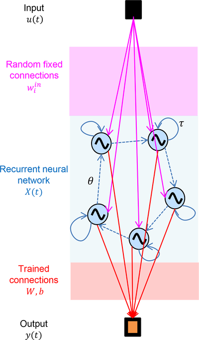
Principle of reservoir computing. The input u(t) is connected via fixed connections to a recurrent neural network, called a reservoir. The reservoir maps the input u(t) into a higher dimensional state X(t), that is, each neuron output is a coordinate of the projected input. The output y(t) is obtained by combining the neuron responses with trained connections W, b.

Implementation of reservoir computing with a single oscillator. (a) The patterns to recognize are discretized sine and square periods. (b) The discrete input u(k) is a time sequence of these sine and square periods, randomly arranged. (c) Preprocessed input J(t) obtained by multiplying u(k) with a fast varying sequence called a mask. This mask varies every θ and represents the coupling between the input and each virtual neuron of the reservoir. (d) x(t) is the oscillator response in oscillation amplitude to the preprocessed input J(t). The oscillator plays the role of all virtual neurons one after the other, every θ. (e) The higher dimension mapping X(k) of the input u(k) can be retrieved in the different sequences of x(t) of duration τ. In our experiment the oscillator emulates n = 24 neurons, θ = 180 ns, τ = 4. 3 μs. (f) Then the output y(k) is reconstructed offline on a computer by combining linearly the responses of the virtual neurons y(k) = W. X(k) + b. (g) If the output y(k) is less than 0.5, the input u(k) is classified as a sine, otherwise it is classified as a square.

(a) Pattern to recognize: the time-varying input u(k) used to evaluate the delayed feedback spin torque oscillator is composed of sine and square sequences. The 8 inputs from sine are designated as si1–8 and the 8 inputs of a square are designated as sq1–8. (b) Comparison of the average experimental time traces of x(t) without feedback for si7 (represented in orange) and sq5–8 (represented in cool colors, blues and greens). The shaded regions indicate twice the standard deviation of x(t) for sq5, sq8, and si7. The operating point is 300 mT and −6.5 mA. (c) Similar comparison with feedback.

(a) 2D visualization of the higher dimension mapping X(k) obtained from experiment for all the different inputs u(k) without feedback. The operating point is 300 mT and −6.5 mA. The separation between sine and square cases is the vertical black solid x = 0.5. For a perfect recognition, points corresponding to sine input should be left to this line and points corresponding to square input should be to the right. Without feedback, the points for si7 (orange) and si3 (yellow) are mixed up with the corresponding square cases. The error rate is 10.8 % in the test phase (69 errors). Five clusters are observed corresponding to the five different input values. These clusters are highlighted by grey ellipses and denominated by the letters a to e. (b) 2D visualization of the higher dimension mapping X(k) obtained from experiment for all the different inputs u(k) with feedback. The operating point is 300 mT and −6.5 mA. Thirteen clusters are observed confirming that feedback enables the oscillator to separate inputs by remembering sequences of two consecutive inputs. These clusters highlighted by grey ellipses are denominated by the numbers 1 to 13. The points for si7 and si3 are different from the square cases and fall to the left of the vertical separation line. The final classification is almost perfect with only 0.16 % error rate (one error) during the test phase.

Reduction of errors on the ambiguous cases si3 and si7 due to feedback depending of the operating point, Eq. (1): this reduction of the error is evaluated on the training set. The number of suppressed errors is renormalized by the total number of errors on the training set without feedback. Brighter colors indicate high reduction of the error. The magnetic field is swept from 200 mT to 600 mT and the DC current is swept from −2 mA to −7 mA. In 90 % of operating points, feedback helps distinguishing si3 and si7 during the training phase. Error reduction is high for high DC current (larger than −4 mA) and magnetic field between 250 mT and 400 mT.

Normalized noise level as a function of the operating point: the magnetic field is swept from 200 mT to 600 mT and the DC current is swept from −2 mA to −7 mA. At low field (200 mT to 400 mT) and low current (−2 mA to −5 mA) the noise level in the oscillation amplitude response is high. Areas of high noise (brighter color) correspond to areas where the feedback is not efficient at suppressing errors.

Proportion of si3 and si7 misclassified on training set without feedback, Eq. (2): the magnetic field is swept from 200 mT to 600 mT and the DC current is swept from −2 mA to −7 mA. For 600 mT and −5 mA, si3 and si7 are well classified even without feedback (only 17 % error). Other operating points exhibit good performance (orange and red areas).

Global error reduction on the training set due to the feedback as a function of the operating point, Eq. (3): the number of suppressed errors is renormalized by the total number of errors on the training set without feedback. The magnetic field is swept from 200 mT to 600 mT and the DC current is swept from −2 mA to −7 mA. Feedback reduces the error rate on the training set only in 66 % of the cases. The feedback thus generates new errors in at least 24 % of the bias points. Brighter colors indicate high reduction of the error. Error reduction is high for high DC current (larger than −4 mA) and fields between 250 mT and 400 mT.

Global error rate reduction due to feedback on the test set as a function of the operating point, Eq. (4): the number of suppressed errors is renormalized by the total number of errors on the test set without feedback. The magnetic field is swept from 200 mT to 600 mT and the DC current is swept from −2 mA to −7 mA. Global error rate reduction during test phase is in good agreement with the improvement during training phase. Feedback improves the result in 60 % of the cases during the test phase. Brighter colors indicate high reduction of the error. Error reduction is high for high DC current (larger than −4 mA) and fields between 250 mT and 400 mT.

Resistance as a function of the in-plane applied magnetic field.

Color maps of the (a) frequency, (b) linewidth and (c) emitted microwave power of the oscillator as a function of dc current and applied perpendicular magnetic field.
References
-
- Hochreiter S and Schmidhuber J, Long Short-term Memory, Neural Comput. 9, 1735 (1997). - PubMed
-
- Schuster M and Paliwal KK, Bidirectional recurrent neural networks, IEEE Trans. Signal Process. 45, 2673 (1997).
Grants and funding
LinkOut - more resources
Full Text Sources