. 2020 Feb 19:14:120.
doi: 10.3389/fnins.2020.00120. eCollection 2020.

Long-Term Home-Use of Sensory-Motor-Integrated Bidirectional Bionic Prosthetic Arms Promotes Functional, Perceptual, and Cognitive Changes

Affiliations

Long-Term Home-Use of Sensory-Motor-Integrated Bidirectional Bionic Prosthetic Arms Promotes Functional, Perceptual, and Cognitive Changes

Jonathon S Schofield et al. Front Neurosci. .

Abstract

Cutaneous sensation is vital to controlling our hands and upper limbs. It helps close the motor control loop by informing adjustments of grasping forces during object manipulations and provides much of the information the brain requires to perceive our limbs as a part of our bodies. This sensory information is absent to upper-limb prosthesis users. Although robotic prostheses are becoming increasingly sophisticated, the absence of feedback imposes a reliance on open-loop control and limits the functional potential as an integrated part of the body. Experimental systems to restore physiologically relevant sensory information to prosthesis users are beginning to emerge. However, the impact of their long-term use on functional abilities, body image, and neural adaptation processes remains unclear. Understanding these effects is essential to transition sensate prostheses from sophisticated assistive tools to integrated replacement limbs. We recruited three participants with high-level upper-limb amputation who previously received targeted reinnervation surgery. Each participant was fit with a neural-machine-interface prosthesis that allowed participants to operate their device by thinking about moving their missing limb. Additionally, we fit a sensory feedback system that allowed participants to experience touch to the prosthesis as touch on their missing limb. All three participants performed a long-term take-home trial. Two participants used their neural-machine-interface systems with touch feedback and one control participant used his prescribed, insensate prosthesis. A series of functional outcome metrics and psychophysical evaluations were performed using sensate neural-machine-interface prostheses before and after the take-home period to capture changes in functional abilities, limb embodiment, and neural adaptation. Our results demonstrated that the relationship between users and sensate neural-machine-interface prostheses is dynamic and changes with long-term use. The presence of touch sensation had a near-immediate impact on how the users operated their prostheses. In the multiple independent measures of users' functional abilities employed, we observed a spectrum of performance changes following long-term use. Furthermore, after the take-home period, participants more appropriately integrated their prostheses into their body images and psychophysical tests provided strong evidence that neural and cortical adaptation occurred.

Keywords: human-machine interface; perceptual engineering; prosthesis; sensory restoration; take-home trial.


Figures

FIGURE 1
FIGURE 1
Photographs of the closed-loop NMI prosthesis system created for and used by the participant with a shoulder disarticulation (SD). Touch tactors placed in the chest plate are shown in the left panel, while dome electrodes and bump switches used for control are shown in the right main panel. Touch tactors extended when sensors embedded in the prosthetic hand detected touch. Close-up views of the touch tactors extended are shown in the top inset, and an unmounted tactor in the rest and extended position is shown in the bottom inset.
FIGURE 2
FIGURE 2
Regions of the hand where the participant with a shoulder disarticulation (SD), the participant with a transhumeral amputation (TH), and the control participant (CTRL) felt sensation when their reinnervated skin was touched in the initial visit and final visit are shown. Red shading indicates where sensation was felt on the ventral side of their hand, and blue shading indicates where sensation was felt on the dorsal side of their hand. The intensity of the shaded areas indicates the proportion of probed locations on the reinnervated skin for which sensation was perceived at that location on the missing hand. (A) Shows sensations reported from all points tested on each individual participant’s reinnervated skin. (B) Shows the reported sensations arising from the reinnervated skin near/surrounding the tactor locations. The areas of each participant’s prosthetic hand that were instrumented are shown in the top row. The locations of the strain gauges in the digits of the SensorHand Speed are shown in green on the schematic of the prosthetic hand. The regions where the sensors responded are shown on the cosmesis in green for the strain gauges and purple for the force sensitive resistors.
FIGURE 3
FIGURE 3
Responses to touch mapping for the participant with a shoulder disarticulation (SD). The initial visit is shown on the left while the final visit is shown on the right. Sensations that were reported as projected to the ventral or dorsal side of the missing hand are shown in red and blue, respectively. The locations of the tactor heads that pushed on SD’s skin are depicted as shaded circles and the tactor motor bodies are outlined with dotted lines; these correspond to sensors located on the prosthesis palm (yellow), thumb (D1, light blue) index finger (D2, medium blue), middle finger (D3, magenta), ring finger (D4, tan), and little finger (D5, light green). Locations of EMG electrodes near the reinnervated skin are portrayed as dark green circles. The line drawings below the maps for each visit depict the locations of the points mapped and the tactor heads (colored circles) on SD’s upper chest. The proportional (gold markers) and tap (mauve markers) gains for each of the six tactors are shown in the panel in the bottom center.
FIGURE 4
FIGURE 4
Initial responses to touch mapping for the participant with a transhumeral amputation (TH). Sensations that were reported as projected to the ventral or dorsal side of the missing hand are shown in red and blue, respectively. The locations of the tactor heads that pushed on TH’s skin are depicted as shaded circles and the tactor motor bodies are outlined with dotted lines; these correspond to sensors located on the prosthesis palm (yellow), thumb (D1, light blue) index finger (D2, medium blue), middle finger (D3, magenta), ring finger (D4, tan), and little finger (D5, light green). The line drawing on the upper left depicts the locations of the points mapped and the tactor heads (colored circles) on TH’s upper arm. The proportional (gold markers) and tap (mauve markers) gains for each of the six tactors are shown in the panel in the top right. Bright green lines and arrows are provided to help orient the reader between the points drawn on the residual limb and the maps. Note that the wider spacing of the maps from the distal end of the residual limb is a result of projecting the surface of the three-dimensional residual limb onto a two-dimensional page; touch mapping points were uniformly spaced around the residual limb. Also note EMG control electrode locations are not depicted as this participant used a pattern recognition EMG control system and silicone liner. Therefore, effective control is relatively insensitive to electrode location, and electrode position may vary with respect to tactors with each donning.
FIGURE 5
FIGURE 5
Final responses to touch mapping for the participant with a transhumeral amputation (TH). Sensations that were reported as projected to the ventral or dorsal side of the missing hand are shown in red and blue, respectively. The locations of the tactor heads that pushed on TH’s skin are depicted as shaded circles and the tactor motor bodies are outlined with dotted lines; these correspond to sensors located on the prosthesis palm (yellow), thumb (D1, light blue) index finger (D2, medium blue), middle finger (D3, magenta), ring finger (D4, tan), and little finger (D5, light green). The line drawing on the upper left depicts the locations of the points mapped and the tactor heads (colored circles) on TH’s upper arm. The proportional (gold markers) and tap (mauve markers) gains for each of the six tactors are shown in the panel in the top right. Bright green lines and arrows are provided to help orient the reader between the points drawn on the residual limb and the maps. Note that the wider spacing of the maps from the distal end of the residual limb is a result of projecting the surface of the three-dimensional residual limb onto a two-dimensional page; touch mapping points were uniformly spaced around the residual limb. Also note EMG control electrode locations are not depicted as this participant used a pattern recognition EMG control system and silicone liner. Therefore, effective control is relatively insensitive to electrode location, and electrode position may vary with respect to tactors with each donning.
FIGURE 6
FIGURE 6
Responses to touch mapping for the control participant (CTRL). The initial visit is shown on the left while the final visit is shown on the right. Sensations that were reported as projected to the ventral or dorsal side of the missing hand are shown in red and blue, respectively. The locations of the tactor heads that pushed on CTRL’s skin are depicted as shaded circles and the tactor motor bodies are outlined with dotted lines; these correspond to sensors located on the prosthesis thumb (D1, light blue) and index finger (D2, medium blue). Locations of EMG electrodes near the reinnervated skin are portrayed as dark green circles. The line drawings below the maps for each visit depict the locations of the points mapped and the tactor heads (colored circles) on CTRL’s upper arm. The proportional (gold markers) and tap (mauve markers) gains for each of the two tactors are shown below the maps. Note that one point was probed on the posterior side of the residual limb; the map showing the response for that point is shown in the box labeled ‘Posterior.’ Also note, while the number of tested points varied between initial and final mapping sessions, the points tested in the final mapping session were an expanded data set. This expansion captured the sensations reported over the same area of reinnervated skin but with greater resolution. Subsequent analyses based on data from these points (Figure 2) were designed to mathematically accommodate this methodological difference. All points tested are shown, regardless of whether or not the participant reported feeling sensation projected to their missing hand when touched at that location.
FIGURE 7
FIGURE 7
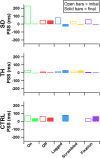
Point of subjective simultaneity (PSS) is presented for the participant with a shoulder disarticulation (SD, top row), the participant with a transhumeral amputation (TH, center row), and the control participant (CTRL, bottom row) for their visits before (open bars) and after (filled bars) the take-home period. From left to right, participants’ results from the touch-on (green), touch-off (red), lagged (blue), scrambled (yellow), and fixation (purple) conditions are shown. Values further from zero indicate greater asymmetry in the PSS between the intact and amputated sides.
FIGURE 8
FIGURE 8
The degree of agreement with questionnaire statements is shown for the participant with a shoulder disarticulation (SD, top row, circles), the participant with a transhumeral amputation (TH, center row, squares), and the control participant (CTRL, bottom row, triangles) in their visit before (open markers) and after (filled markers) the take-home period. Responses to control questions are provided in Supplementary Figure 1. All participants responded below the cutoff for agreement to the control questions. Markers are colored according to touch feedback condition: touch-on (green), touch-off (red), lagged (blue), scrambled (yellow), and fixation (purple). Participants were considered to have embodied their prosthesis if their agreement with embodiment questions was greater than or equal to one (Kalckert and Ehrsson, 2012), indicated by the dashed line.
FIGURE 9
FIGURE 9
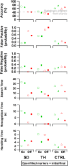
From top to bottom: accuracy, false positive rate, false negative rate, search time, recognition time, and handling time data are presented. Results are shown for the participant with a shoulder disarticulation (SD, left column, circles), the participant with a transhumeral amputation (TH, center column, squares), and the control participant (CTRL, right column, triangles) in their visit before (open markers) and after (filled markers) the take-home period. Data are presented for the touch-on (green) and touch-off (red) conditions. The gray dashed line in the accuracy plot indicates the smallest statistically detectable change (41%) from chance accuracy (33%).
FIGURE 10
FIGURE 10
Results are shown for the participant with a shoulder disarticulation (SD, left column, circles), the participant with a transhumeral amputation (TH, center column, squares), and the control participant (CTRL, right column, triangles) in their visit before (open markers) and after (filled markers) the take-home period. Data presented are from the touch-on (green) and touch-off (red) conditions. The dashed line and shading indicate the area in which, statistically, there was not reliable grasp production (i.e., force greater than zero). Note that since TH’s initial visit did not include precision trials, the peak precision values for the initial visit may be slightly underestimated. Also note that since TH did not successfully handle any objects without touch feedback in the final visit, peak precision and throughput are undefined for that case.
FIGURE 11
FIGURE 11
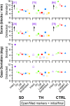
Score and gaze deviation during the Box and Block task are presented in the top two and bottom two rows, respectively. In both pairs, the top row shows the results during the standard task while the bottom row shows the results during the trials when a visual distractor was present. Results are shown for the participant with a shoulder disarticulation (SD, left column, circles), the participant with a transhumeral amputation (TH, center column, squares), and the control participant (CTRL, right column, triangles) in their visit before (open markers) and after (filled markers) the take-home period. Participants’ performance with their intact side are presented on the left (purple), followed by performance with the amputated side during the (from left to right) touch-on (green), touch-off (red), lagged (blue), and scrambled (yellow) conditions. Able-bodied scores that are outside of the y-axis range are shown in brackets.
FIGURE 12
FIGURE 12
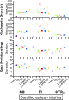
Score and gaze deviation during the Clothespin Relocation task are presented in the top two and bottom two rows, respectively. In both pairs, the top row shows the results during the standard task while the bottom row shows the results during the trials when a visual distractor was present. Results are shown for the participant with a shoulder disarticulation (SD, left column, circles), the participant with a transhumeral amputation (TH, center column, squares), and the control participant (CTRL, right column, triangles) in their visit before (open markers) and after (filled markers) the take-home period. Participants’ performance with their intact side are presented on the left (purple), followed by performance with the amputated side during the (from left to right) touch-on (green), touch-off (red), lagged (blue), and scrambled (yellow) conditions.

References

    1. Aimola Davies A. M., White R. C. (2013). A sensational illusion: vision-touch synaesthesia and the rubber hand paradigm. Cortex 49 806–818. 10.1016/j.cortex.2012.01.007 - DOI - PubMed
    1. Antfolk C., D’Alonzo M., Controzzi M., Lundborg G., Rosen B., Sebelius F., et al. (2013). Artificial redirection of sensation from prosthetic fingers to the phantom hand map on transradial amputees: vibrotactile versus mechanotactile sensory feedback. IEEE Trans. Neural Syst. Rehabil. Eng. 21 112–120. 10.1109/TNSRE.2012.2217989 - DOI - PubMed
    1. Beckler D. T., Thumser Z. C., Schofield J. S., Marasco P. D. (2019). Using sensory discrimination in a foraging-style task to evaluate human upper-limb sensorimotor performance. Sci. Rep. 9:5806. 10.1038/s41598-019-42086-0 - DOI - PMC - PubMed
    1. Belter J. T., Segil J. L., Dollar A. M., Weir R. F. (2013). Mechanical design and performance specifications of anthropomorphic prosthetic hands: a review. J. Rehabil. Res. Dev. 50 599–618. 10.1682/JRRD.2011.10.0188 - DOI - PubMed
    1. Boccia M., Di Vita A., Palermo L., Nemmi F., Traballesi M., Brunelli S., et al. (2019). Neural modifications in lower limb amputation: an fMRI study on action and non-action oriented body representations. Brain Imaging Behav. 1–10. 10.1007/s11682-019-00142-3 [Epub ahead of print]. - DOI - PubMed