Review
. 2020 Mar 5;11(3):271.
doi: 10.3390/mi11030271.

Engineering Microneedles for Therapy and Diagnosis: A Survey

Affiliations
Review

Engineering Microneedles for Therapy and Diagnosis: A Survey

Liping Xie et al. Micromachines (Basel). .

Abstract

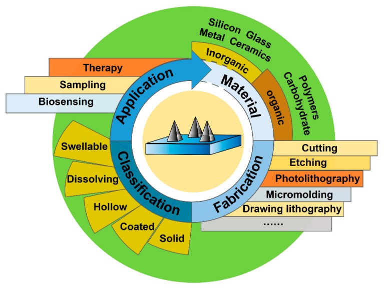
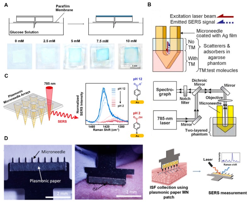
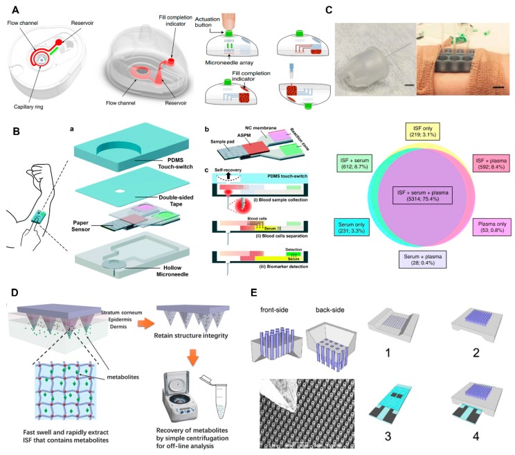
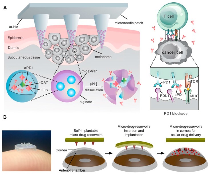
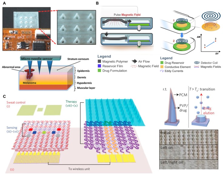
Microneedle (MN) technology is a rising star in the point-of-care (POC) field, which has gained increasing attention from scientists and clinics. MN-based POC devices show great potential for detecting various analytes of clinical interests and transdermal drug delivery in a minimally invasive manner owing to MNs' micro-size sharp tips and ease of use. This review aims to go through the recent achievements in MN-based devices by investigating the selection of materials, fabrication techniques, classification, and application, respectively. We further highlight critical aspects of MN platforms for transdermal biofluids extraction, diagnosis, and drug delivery assisted disease therapy. Moreover, multifunctional MNs for stimulus-responsive drug delivery systems were discussed, which show incredible potential for accurate and efficient disease treatment in dynamic environments for a long period of time. In addition, we also discuss the remaining challenges and emerging trend of MN-based POC devices from the bench to the bedside.

Keywords: diagnosis; drug delivery; microneedle; point of care.


Conflict of interest statement

The authors declare no conflict of interest.

Figures

Figure 1
Figure 1
Schematic illustration of microneedles (MNs) commonly used in biomedical diagnosis and therapy (authors’ own work).
Figure 2
Figure 2
Schematic illustration of fabrication methods. (A) Procedure for the fabrication of a hollow MN by photolithography (reproduced with permission from the authors of [91]). (B) Typical process of MN fabrication via micromolding (authors’ own work). (C) Steps for producing primary MN array by drawing lithography(reproduced with permission from the authors of [88]). PDMS, polydimethylsiloxane.
Figure 3
Figure 3
Schematic illustration of MN categories and their common application fields (authors’ own work).
Figure 4
Figure 4
(A) Schematic illustration of dissolvable polyvinylpyrrolidone (PVP) layer/ZnO NWs/Pt nanostructure modified stainless MN. PVP coating provides protection during skin penetration, and rapidly dissolves after penetration, exposing sensitive probe for detection (reproduced with permission from the authors of [44]). (B) Schematic of a continuous minimally invasive alcohol sensor. (reproduced with permission from the authors of [21]) CE, counter electrode; WE, working electrode; RE, reference electrode. (C) Schematic presentation of three kinds of coating methods for MNs fabrication and average Imax of sensors gained by these methods in glucose monitoring experiment, which indicates the maximum limit of the amperometric current response and the maximum enzymatic reaction rate at the saturation point (reproduced with permission from the authors of [119]). DL, drop-cast method; SL, layer-by-layer method; SM, simultaneous spray mixing method; TTF, tetrathiafulvalene; GOx, glucose oxidase; GA, glutaraldehyde; PPD, poly(o-phenylenediamine); NWs, nanowires.
Figure 5
Figure 5
(A) Schematic illustration of a paper-based rapid colorimetric glucose sensor (top) and digital photographs of glucose-responsive backplates after addition of different concentrations of glucose(down) (reproduced with permission from the authors of [122]). (B) Schematic illustration of Ag-coated MN in two-layered human skin mimic (top) and Raman system for surface-enhanced Raman scattering (SERS) measurement (down) (reproduced with permission from the authors of [126]). TM, test molecules. (C) Schematic representation of plasmonic MN array for in situ pH measurement by SERS (reproduced with permission from the authors of [127]). (D) Photographs of MN patch with a plasmonic paper (left) and interstitial fluid (ISF) collection through MN penetrating into hairless rat (middle) and schematic illustration of SERS analysis of the plasmonic paper MN with target (right) (reproduced with permission from the authors of [128]).
Figure 6
Figure 6
(A) Schematic illustration of a self-powered one-touch blood collector (left) and collection steps (right) (reproduced with permission from the authors of [34]). (B) Schematic illustration of one-touch-activated blood multi-diagnostic system. (reproduced with permission from the authors of [131]). ASPM, asymmetric polysulfone membrane; NC, nitrocellulose. (C) Hollow MN-based ISF collector (top-left) and MN holders attached to skin for ISF extraction (middle-left) and similarity of RNA species detected in ISF, serum, and plasma samples (down) (reproduced with permission from the authors of [133]). (D) Schematic of MeHA swellable MN designed for ISF collection (reproduced with permission from the authors of [17]). (E) Schematic illustration of silicon hollow MN-based ISF collector and its scanning electron microscope (SEM) image. Schematic illustrations including the front-side (1), back-side (2) of MN chip, real-time glucose measurement chip (3), and usage of the two chips (4) (right) (reproduced with permission from the authors of [34]).
Figure 7
Figure 7
(A) Schematic illustration of GOx and catalase (CAT) assisted anti-PD-1 delivery by nanoparticle loaded dissolving MN (reproduced with permission from the authors of [141]). (B) Schematic illustration of self-implantable double-layered MN in ocular application and real product photograph. (reproduced with permission from the authors of [144]).
Figure 8
Figure 8
(A) Photograph of MN integrated with flexible electronics (top) and schematic illustration of melanoma biomarker detection using MN (down) (reproduced with permission from the authors of [164]). (B) Schematic illustration of pneumatic-hydraulic actuator system used for wireless drug delivery (left) and related inductive sensing principal (right) (reproduced with permission from the authors of [165]). (C) Schematic illustration of diabetes sensing and therapy patch (left), drug releasing principal of MN (right top), and photograph of heater controlled stepwise MN dissolution (right down) (reproduced with permission from the authors of [166]).

Similar articles

Cited by

References

    1. Razmi N., Hasanzadeh M. Current advancement on diagnosis of ovarian cancer using biosensing of CA 125 biomarker: Analytical approaches. TrAC Trends Anal. Chem. 2018;108:1–12. doi: 10.1016/j.trac.2018.08.017. - DOI
    1. Shafiee A., Ghadiri E., Kassis J., Pourhabibi Zarandi N., Atala A. Biosensing Technologies for Medical Applications, Manufacturing, and Regenerative Medicine. Curr. Stem Cell Rep. 2018;4:105–115. doi: 10.1007/s40778-018-0123-y. - DOI
    1. Markets and Markets. Wearable Medical Devices Market by Device (Diagnostic (Heart, Pulse, BP, Sleep), Therapeutic (Pain, Insulin, Rehabilitation)), Application (Sport, Fitness, RPM), Type (Smartwatch, Patch), Distribution Channel (Pharmacy, Online) - Global Forecast to 2022. [(accessed on 1 March 2020)]; Available online: https://www.marketsandmarkets.com/Market-Reports/wearable-medical-device....
    1. Quesada-González D., Merkoçi A. Nanomaterial-based devices for point-of-care diagnostic applications. Chem. Soc. Rev. 2018;47:4697–4709. doi: 10.1039/C7CS00837F. - DOI - PubMed
    1. Ma G., Wu C. Microneedle, bio-microneedle and bio-inspired microneedle: A review. J. Control Release. 2017;251:11–23. doi: 10.1016/j.jconrel.2017.02.011. - DOI - PubMed

LinkOut - more resources