Review
. 2020 Mar 12;22(1):19.
doi: 10.1186/s12968-020-00610-6.

Standardized image interpretation and post-processing in cardiovascular magnetic resonance - 2020 update : Society for Cardiovascular Magnetic Resonance (SCMR): Board of Trustees Task Force on Standardized Post-Processing

Affiliations
Review

Standardized image interpretation and post-processing in cardiovascular magnetic resonance - 2020 update : Society for Cardiovascular Magnetic Resonance (SCMR): Board of Trustees Task Force on Standardized Post-Processing

Jeanette Schulz-Menger et al. J Cardiovasc Magn Reson. .

Abstract

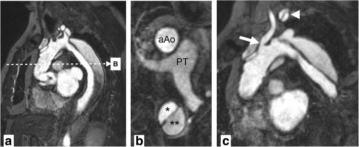
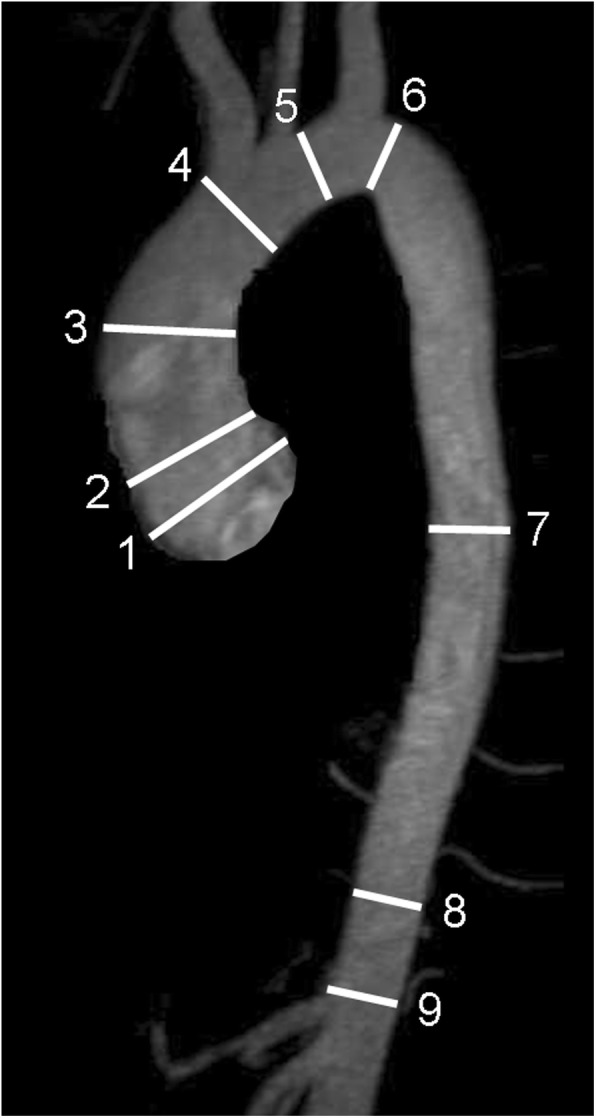
With mounting data on its accuracy and prognostic value, cardiovascular magnetic resonance (CMR) is becoming an increasingly important diagnostic tool with growing utility in clinical routine. Given its versatility and wide range of quantitative parameters, however, agreement on specific standards for the interpretation and post-processing of CMR studies is required to ensure consistent quality and reproducibility of CMR reports. This document addresses this need by providing consensus recommendations developed by the Task Force for Post-Processing of the Society for Cardiovascular Magnetic Resonance (SCMR). The aim of the Task Force is to recommend requirements and standards for image interpretation and post-processing enabling qualitative and quantitative evaluation of CMR images. Furthermore, pitfalls of CMR image analysis are discussed where appropriate. It is an update of the original recommendations published 2013.

Keywords: Heart; Image interpretation; Magnetic resonance imaging; Post-processing; Recommendations.


Conflict of interest statement

The authors declare that they have no competing interests.

Figures

Fig. 1
Fig. 1
Left ventricular (LV) chamber quantification. For LV chamber quantification, the endocardial (blue) and epicardial (yellow) contours are delineated in diastole (left) and systole (right) in a stack of short axis slices that cover the whole left ventricle. a and b illustrate the approach with inclusion of the papillary muscles as part of the LV volume. c and d show the approach with exclusion of the papillary muscles from the LV volume
Fig. 2
Fig. 2
Right ventricular (RV) chamber quantification. For RV volume quantification, the endocardial (red) contours are delineated in diastole (a) and systole (b) in a stack of transaxial slices covering the whole RV (top). Alternatively, a stack of short axis slices can be used (c, d). Here, the yellow contours indicate the RV in diastole (c) and systole (d); the RV is contoured following the LV analysis (in c and d, red / green contours indicate endocardial / epicardial borders of the LV) and with reference to the LV
Fig. 3
Fig. 3
Perfusion imaging. a Perfusion defect in the inferior segments (yellow arrow). Note defect is predominantly subendocardial, affects the perfusion territory of the right coronary artery and is more than one pixel wide. b Dark banding artifact (yellow arrow). Note defect is very dark, occurs already before contrast reaches the myocardium, is seen in the phase encoding direction (right-left in this case), and is approximately one pixel wide. c Positioning of endocardial (red) and epicardial (green) contours and a region-of-interest (ROI) in the LV blood pool (blue) for semiquantitative or quantitative analysis of perfusion data
Fig. 4
Fig. 4
Late gadolinium enhancement (LGE) imaging. Role of inversion time in LGE imaging: On the left panel which is a magnitude (non-PSIR) LGE image, normal myocardium has a faint etched appearance (darkest at the border with higher signal intensity centrally) signifying an inversion time that was set too short and which will lead to underestimation of LGE. On the right panel, the image was repeated with a longer inversion time and demonstrates a larger LGE zone in the inferior wall. For non-PSIR magnitude imaging, always use the longest inversion time possible that still nulls normal myocardium
Fig. 5
Fig. 5
Native T1 map in a patient with acute myocarditis illustrating T1 elevation in the subepicardial lateral LV wall (modified from [64])
Fig. 6
Fig. 6
T2-weighted image (short-tau inversion recovery, STIR) in a midventricular short axis view with increased SI in the inferolateral and lateral segments in acute myocarditis
Fig. 7
Fig. 7
T2* imaging to assess myocardial iron overload. a T2* scan of a normal heart showing slow signal loss with increasing TE. b Decay curve for normal heart. T2* = 33.3 ms. c Heavily iron overloaded heart. Note there is substantial signal loss at TE = 9.09. d Decay curve for heavily iron overloaded heart showing rapid signal loss with increasing TE. The curve plateaus as myocardial SI falls below background noise. e Values for higher TEs are removed (truncation method) resulting in a better curve fit and a lower T2* value
Fig. 8
Fig. 8
Quantification of blood flow. (top) Contours were drawn delineating the aortic lumen at the sinotubular level during all 20 phases of the cardiac cycle to assess aortic flow. (bottom) Flow curves from measurements in the ascending aorta and in the pulmonary artery in a patient with ventricular septal defect showing a left-to-right shunt
Fig. 9
Fig. 9
Magnetic resonance angiography. Stanford A aortic dissection after surgical repair with graft of ascending aorta. Panel a shows a source image of breath-held 3D gradient recalled echo sequence after contrast injection. Multiplanar reformats in axial orientation (b) at the level of the pulmonary trunk (PT) show a normally perfused ascending aorta graft (aAo) and persistent dissection in descending aorta with true (*) and false (**) lumina. Double oblique reformat (c) shows narrowing at the origin of the left common carotid artery (arrow) and dissection membrane propagating into the left subclavian artery (arrowhead) with perfusion of both lumina
Fig. 10
Fig. 10
Anatomic landmarks for standardized reporting of diameters of the aorta at the level of sinuses of Valsalva (1), sinotubular junction (2), mid-ascending aorta (3), proximal to brachiocephalic trunk (4), between left common carotid and left subclavian arteries (5), distal to left subclavian artery (6), mid-descending aorta (7), diaphragm (8), abdominal aorta above celiac trunk (9). (Adapted from [87])

References

    1. Schulz-Menger J, Bluemke DA, Bremerich J, Flamm SD, Fogel MA, Friedrich MG, et al. Standardized image interpretation and post processing in cardiovascular magnetic resonance: Society for Cardiovascular Magnetic Resonance (SCMR) Board of Trustees Task Force on Standardized Post Processing. J Cardiovasc Magn Reson. 2013;15:35. doi: 10.1186/1532-429X-15-35. - DOI - PMC - PubMed
    1. Douglas PS, Hendel RC, Cummings JE, Dent JM, Hodgson JM, Hoffmann U, et al. ACCF/ACR/AHA/ASE/ASNC/HRS/NASCI/RSNA/SAIP/SCAI/SCCT/SCMR 2008 health policy statement on structured reporting in cardiovascular imaging. J Am Coll Cardiol. 2009;53:76–90. doi: 10.1016/j.jacc.2008.09.005. - DOI - PubMed
    1. Hundley WG, Bluemke D, Bogaert JG, Friedrich MG, Higgins CB, Lawson MA, et al. Society for Cardiovascular Magnetic Resonance guidelines for reporting cardiovascular magnetic resonance examinations. J Cardiovasc Magn Reson. 2009;11:5. doi: 10.1186/1532-429X-11-5. - DOI - PMC - PubMed
    1. Kramer CM, Barkhausen J, Bucciarelli-Ducci C, et al. Standardized cardiovascular magnetic resonance imaging (CMR) protocols: 2020 update. J Cardiovasc Magn Reson. 2020;22:17. doi: 10.1186/s12968-020-00607-1. - DOI - PMC - PubMed
    1. Selvadurai BSN, Puntmann VO, Bluemke DA, Ferrari VA, Friedrich MG, Kramer CM, et al. Definition of left ventricular segments for cardiac magnetic resonance imaging. JACC Cardiovasc Imaging. 2018;11:926–928. doi: 10.1016/j.jcmg.2017.09.010. - DOI - PubMed

Publication types

MeSH terms