Review
. 2020 Mar 11;20(6):1569.
doi: 10.3390/s20061569.

Ultrasensitive Magnetic Field Sensors for Biomedical Applications

Affiliations
Review

Ultrasensitive Magnetic Field Sensors for Biomedical Applications

Dmitry Murzin et al. Sensors (Basel). .

Abstract

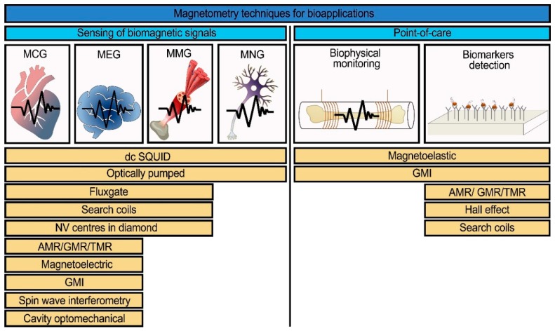
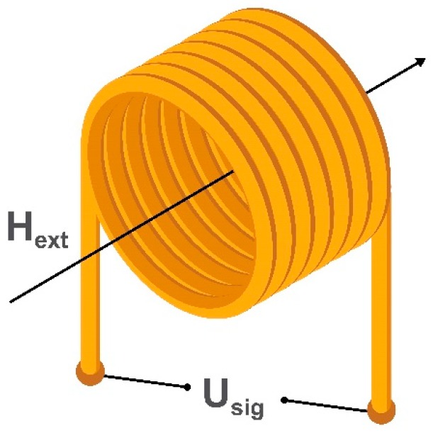
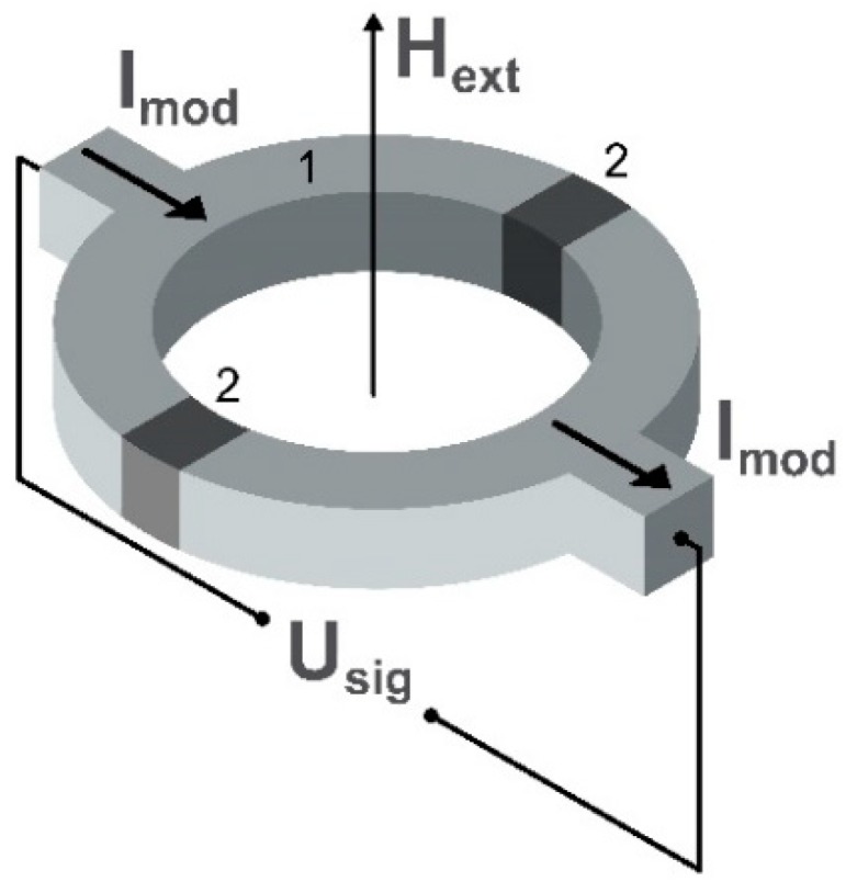
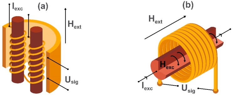
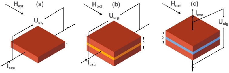
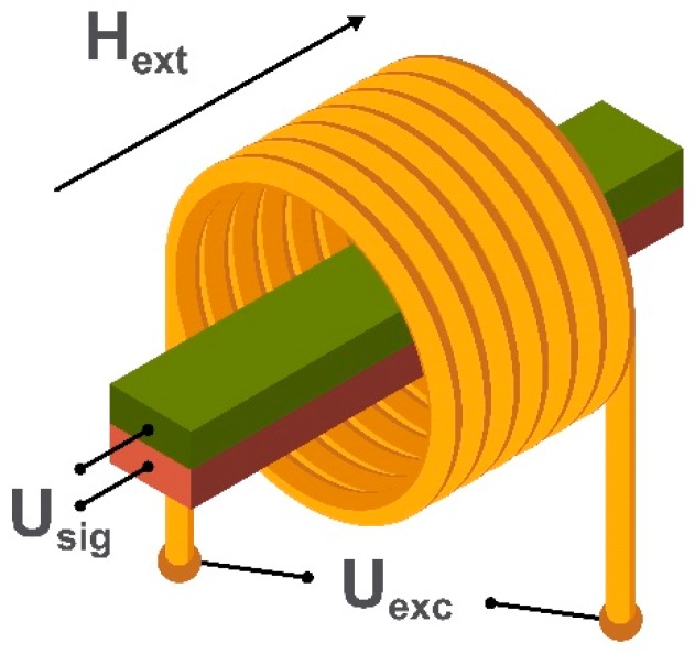
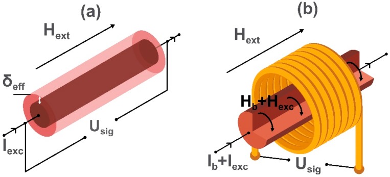
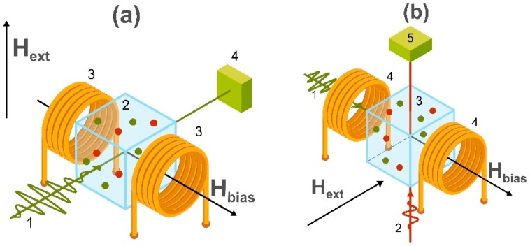
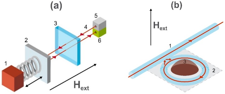
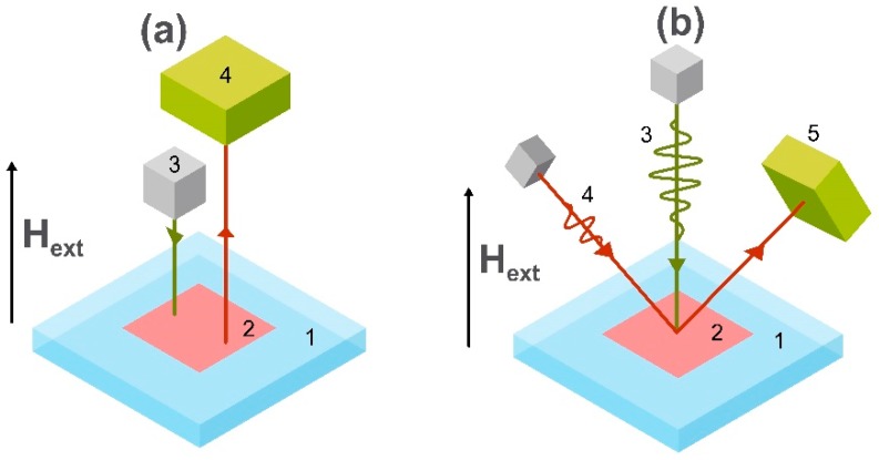
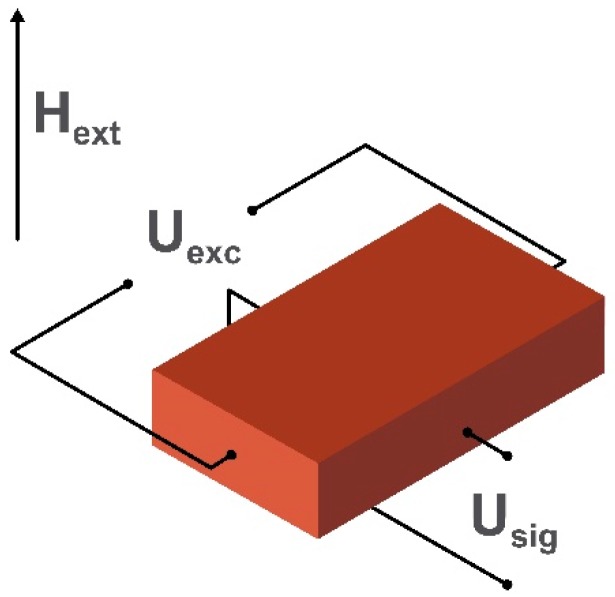
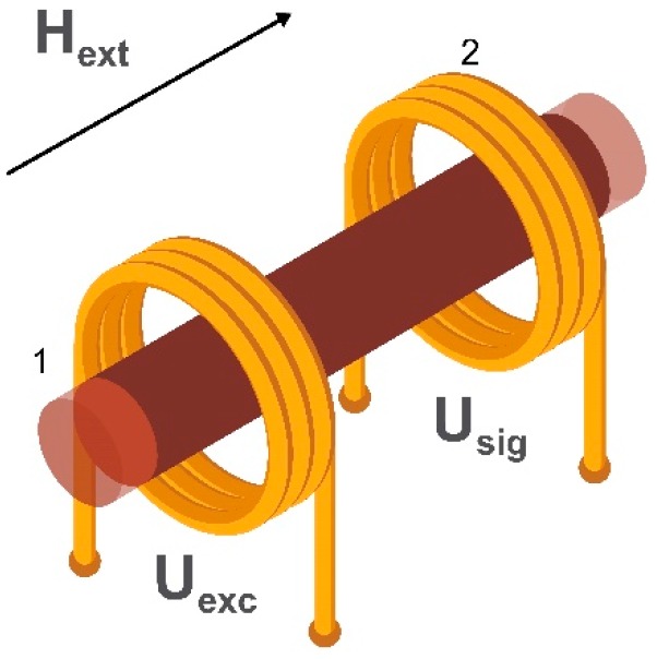
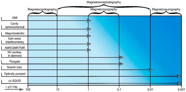
The development of magnetic field sensors for biomedical applications primarily focuses on equivalent magnetic noise reduction or overall design improvement in order to make them smaller and cheaper while keeping the required values of a limit of detection. One of the cutting-edge topics today is the use of magnetic field sensors for applications such as magnetocardiography, magnetotomography, magnetomyography, magnetoneurography, or their application in point-of-care devices. This introductory review focuses on modern magnetic field sensors suitable for biomedicine applications from a physical point of view and provides an overview of recent studies in this field. Types of magnetic field sensors include direct current superconducting quantum interference devices, search coil, fluxgate, magnetoelectric, giant magneto-impedance, anisotropic/giant/tunneling magnetoresistance, optically pumped, cavity optomechanical, Hall effect, magnetoelastic, spin wave interferometry, and those based on the behavior of nitrogen-vacancy centers in the atomic lattice of diamond.

Keywords: biomagnetic fields; biosensors; diagnosis; magnetic field sensors; noninvasive medical procedures; therapeutic application.


Conflict of interest statement

The authors declare no conflict of interest. The funders had no role in the design of the study; in the collection, analyses, or interpretation of data; in the writing of the manuscript, or in the decision to publish the results.

Figures

Figure 1
Figure 1
A list of the common and modern magnetic field sensors with the potential to be used for the detection of biomagnetic signals (magnetocardiography (MCG), magnetoencephalography (MEG), magnetomyography (MMG), magnetoneurography (MNG)) and for point-of-care devices [18,19,20,21,22,23,24,25,26,27,28,29,30,31,32,33,34,35].
Figure 2
Figure 2
Schematic illustration of an induction coil of a search coil magnetometer, where Hext is the applied alternating magnetic field through the coil and Usig is the voltage generated in the induction coil.
Figure 3
Figure 3
Schematic illustration of the sensing element of the dc SQUID (Super Quantum Interference Effect) magnetometer, where Hext is the applied external magnetic field. Usig is the voltage variation detected by the magnetic field-induced imbalance of the current Imod flowing through the two semiconducting loops (1) and the two Josephson junctions (2) of the sensing ring.
Figure 4
Figure 4
Schematic images of the sensing elements: (a) a parallel fluxgate magnetometer and (b) an orthogonal fluxgate magnetometer using a magnetic microwire. Hext is the applied external magnetic field, Iexc is an alternating excitation current producing the excitation magnetic field Hexc, and Usig is the voltage generated in the detection coil.
Figure 5
Figure 5
Schematic images of the sensing elements of (a) anisotropic magnetoresistance, (b) giant magnetoresistance, and (c) tunneling magnetoresistance magnetic field sensors, where Iexc is a current flowing through the film made from ferromagnetic material (AMR element (1)), non-magnetic material (spacer layer in the GMR element (2)) or insulating material (barrier layer in the TMR element (3)), respectively. Usig is a voltage detected in a direction perpendicular to the external magnetic field Hext.
Figure 6
Figure 6
Schematic image of the sensing element of a magnetoelectric magnetometer, where Hext is the applied external magnetic field, and Uexc is the voltage generating an external excitation magnetic field. Usig is the voltage produced by the piezoelectric material which is deposited onto a magnetostrictive ferromagnetic material.
Figure 7
Figure 7
Schematic images of the conventional GMI (a) and off-diagonal GMI (b) magnetic field sensing elements, where Hext is the dc external magnetic field (measured field), Iexc and Hexc are the ac excitation current and field, Ib and Hb are the dc bias current and field, respectively, Usig is the measured output voltage, and δeff is the skin depth of the electric current in the element. The circular bias field Hb is needed in the case of the off-diagonal GMI to eliminate the domain walls in the circular domain structure.
Figure 8
Figure 8
Schematic images of two main geometries of the optically pumped atomic magnetometer. In (a), the measuring scheme includes a circularly polarized pump beam (1) passing through the vapor cell (2) placed into the applied external magnetic field (Hext) and bias magnetic field (Hbias) generated by the Helmholtz coils (3). The detecting system is shown as (4). In (b), the measuring scheme includes a circularly polarized pump (1) and linearly polarized probe beams (2) passing through the vapor cell (3) placed into applied external and bias magnetic fields generated by the Helmholtz coils (4). The probe beam detecting system is shown as (5).
Figure 9
Figure 9
Schematic image of the working principle of the cavity optomechanical system. Panel (a) shows a mechanical resonator consisting of a magnetostrictive material (1) and moving mirror (2) bonded to the Fabry–Pérot optical resonator consisting of a fixed mirror (3), optical path length (4), light emitter (5), and detecting system (6). Panel (b) schematically represents the sensing element of the magnetometer including an optical fiber (1), resonator system (2), and magnetostrictive material (3) which is sensitive to the applied external magnetic field Hext.
Figure 10
Figure 10
Schematic images of two geometries of the sensing elements of magnetometers based on the excitation of nitrogen-vacancy centers in diamond where Hext is the applied external magnetic field. Panel (a) shows the schematic geometry of the continuous illumination protocol where the numbers refer to diamond (1), the nitrogen-vacancy centers in diamond (2), light emitter (3), and the system for detection of the luminescence light (4). Panel (b) represents the schematic image of pulsed illumination and resonance relaxometry protocols, where the numbers refer to diamond (1), the nitrogen-vacancy centers in diamond (2), pump beam (3), probe beam (4), and detecting system (5).
Figure 11
Figure 11
Schematic image of the sensing element of a Hall effect-based magnetometer, where the applied external magnetic field Hext is detected by the Hall voltage Usig orthogonal to an element current produced by a drive voltage Uexc.
Figure 12
Figure 12
Schematic image of the sensing element of the magnetoelastic material-based strain sensor where an applied magnetic field generated by an alternating voltage Uexc in a primary coil (1) causes an alternating voltage Usig induced in a secondary ‘detection’ coil (2).
Figure 13
Figure 13
Schematic image of the sensing element of the spin wave-based magnetic field sensor consisting of a spin waves generator (1) exciting spin waves in two antennas (2) detected by the spin wave detector (3), where Hext and Hbias are the applied out-of-plane and bias in-plane external magnetic fields, respectively.
Figure 14
Figure 14
A chart showing how various magnetic sensor technologies (y-axis) relate to the detection of biomagnetic signals (x-axis). For precise details of the sensors, refer to the text.
Figure 15
Figure 15
Example of a biochip based on magnetic label detection using a magnetic thin-film sensor. The chip consists of an array of probe biomolecules (1) of known identity immobilized onto the surface of the sensor (2), magnetic labels (3) functionalized with target biomolecules (4) that bind to the sensor surface through biomolecular recognition. The magnetic stray field Hbead resulting from the magnetic moment of the label induced by the applied magnetic field Hext is measured by the sensor.

References

    1. Vitol E.A., Novosad V., Rozhkova E.A. Microfabricated magnetic structures for future medicine: From sensors to cell actuators. Nanomedicine. 2012;7:1611–1624. doi: 10.2217/nnm.12.133. - DOI - PMC - PubMed
    1. Mapps D.J. Remote magnetic sensing of people. Sens. Actuators A Phys. 2003;106:321–325. doi: 10.1016/S0924-4247(03)00193-6. - DOI
    1. Strand S.A., Strasburger J.F., Wakai R.T. Fetal magnetocardiogram waveform characteristics. Physiol. Meas. 2019;40:035002. doi: 10.1088/1361-6579/ab0a2c. - DOI - PMC - PubMed
    1. Jensen K., Skarsfeldt M.A., Stærkind H., Arnbak J., Balabas M.V., Olesen S.P., Bentzen B.H., Polzik E.S. Magnetocardiography on an isolated animal heart with a room-temperature optically pumped magnetometer. Sci. Rep. 2018;8:16218. doi: 10.1038/s41598-018-34535-z. - DOI - PMC - PubMed
    1. Sumiya S., Kawabata S., Hoshino Y., Adachi Y., Sekihara K., Tomizawa S., Tomori M., Ishii S., Sakaki K., Ukegawa D., et al. Magnetospinography visualizes electrophysiological activity in the cervical spinal cord. Sci. Rep. 2017;7:2192. doi: 10.1038/s41598-017-02406-8. - DOI - PMC - PubMed

LinkOut - more resources