Review
. 2020 Feb;10(1):45-58.
doi: 10.21037/cdt.2019.12.01.

Role of CT imaging in left atrial appendage occlusion for the WATCHMAN™ device

Affiliations
Review

Role of CT imaging in left atrial appendage occlusion for the WATCHMAN™ device

Mirna Kaafarani et al. Cardiovasc Diagn Ther. 2020 Feb.

Abstract

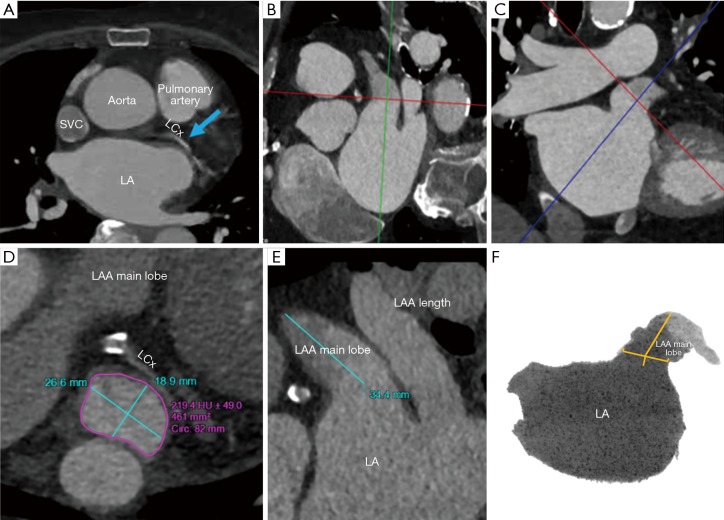
Computed tomography (CT) plays a key role in the peri-procedural planning of left atrial appendage occlusion (LAAO) device placement and post-procedural evaluation. The geometric variability of the interatrial septum, left atrium, and the left atrial appendage morphology can be fully visualized and intuitively appreciated through CT-derived, patient-specific 3D model unique to each individual's anatomy. This review further defines the strengths and limitations of CT peri-procedural imaging in the planning of LAAO.

Keywords: 3D modeling; 3D transesophageal echocardiogram; Left atrial appendage occlusion; WATCHMAN™ device; artifact; computerized tomography.


Conflict of interest statement

Conflicts of Interest: Dr. Wang is a consultant for Boston Scientific and receives research grant funding assigned to employer HFHS from Boston Scientific. Dr. O’Neill has served as a consultant for Edwards Lifesciences, Medtronic, Boston Scientific, Abbott Vascular and St. Jude Medical; and serves on the Board of Directors of Neovasc Inc. Dr Daniels is a consultant for WL Gore. Dr. Saw is a proctor, consultant and has received research grants from Boston Scientific and Abbott Vascular; and is on advisory boards for FEops, Baylis, Abiomed, Bayer, AstraZeneca, and Gore. Sanel Kesinovic and Tony Lamorgese are employees of Boston Scientific. All other authors report no relevant financial disclosures.

Figures

Figure 1
Figure 1
The commercially available sizes of WATCHMAN™ left atrial appendage (LAA) occluder devices. (A) shows a 33 mm WATCHMAN™ device; (B) a 30 mm device; (C) a 27 mm device; (D) a 24 mm device; (E) a 21 mm device.
Figure 2
Figure 2
Fluoroscopic images of WATCHMAN™ device being implanted into the ostium of the left atrial appendage (LAA) with delivery system and access sheath. The yellow arrow shows device face in landing zone of LAA. In (A), the LAA shows anterior chicken wing anatomy, pigtail catheter advanced through WATCHMAN™ access sheath in the appendage, contrast filling anatomy of the appendage. In (B), WATCHMAN™ device catheter is advanced through the WATCHMAN™ access sheath, device deployment is in process with feet exposed and flowering. In (C), WATCHMAN™ device deployed in the appendage. In (D), a fully expanded WATCHMAN™ device silhouette can be seen in landing zone of the LAA. In (E), contrast is injected through the WATCHMAN™ device. In (F), device is released from a device catheter, and the implant is complete.
Figure 3
Figure 3
Surgically ligated left atrial appendage (LAA) seen on pre-LAAO CT. Yellow dotted circle shows the absence of contrast uptake in an area where the main lobe of the LAA existed prior to surgical intervention.
Figure 4
Figure 4
Depictions of different scenarios in which a pre-LAAO CT scan can rule out occlusion. In (A), a CT scan revealed that the ostium is too big to fit even the largest size of available WATCHMAN™ devices. In (B), a CT scan showed that the ostium is too small to fit even the smallest size of available WATCHMAN™ devices. In (C), the small size of ostium shown in image (B) visualized on 3D print highlighted in green dotted line. In (D,E), CT scans revealed that the length of the LAA is too small to fit even the smallest size of available WATCHMAN™ devices. In (F), the small length of the same LAA is shown in images (D) and (E) visualized on 3D print. In (G-I), LAA clots found on pre-LAAO CT scan are shown within yellow dotted line with Image (H) also depicting an LA clot.
Figure 5
Figure 5
Step by step processing of pre-procedural CT images to determine maximum diameter, minimum diameter, and circumference of the left atrial appendage (LAA) ostium as well as the length of the LAA on post-processing software. (A) Step 1: blue arrow indicating the takeoff of the proximal left circumflex artery from the left anterior descending artery is identified using the axial view. (B,C) Step 2: LAA orifice can be identified by the plane connecting the pulmonary vein ridge superiorly to the inferior junction of the left atrium and the LAA at the level of the left circumflex coronary artery. (B) shows the landing zone from a sagittal view, and (C) from a coronal view. (D,E) Step 3: (D) shows the maximum and minimum diameter (shown by turquoise lines), area, and circumference (shown by magenta encircling) of the landing zone in an axial viewport. In (E), the length of the LAA from landing zone to distal tip is measured and shown by turquoise line. (F) Step 4: An inverted maximal-intensity projection in which the length is drawn from the center of the LAA ostium oriented towards the distal tip of the main lobe shown by yellow lines. This shows is used to simulate the LAA intraprocedural angiogram.
Figure 6
Figure 6
Single, double, and anterior configuration of catheters used to implant WATCHMAN™ device in landing zone. Catheters labeled A show a single configuration, B shows double, and C shows anterior.
Figure 7
Figure 7
Diversity of shapes and sizes of the left atrial appendage (LAA) shown by 3D models. These are 3D prints modeled 1:1 after patient anatomy as part of the pre-procedural case planning. Quarter for scale.
Figure 8
Figure 8
Catheter configurations used to implant WATCHMAN™ device. Single, double, and anterior configuration of catheters used to implant WATCHMAN™ device by being thread through the fossa ovalis through the left atrium to the ostium of the left atrial appendage (LAA). The single configuration is shown in (A), the double in (B), the anterior in (C).
Figure 9
Figure 9
Successful left atrial appendage (LAA) occlusion by WATCHMAN™ seen on a 45-day post-LAA occlusion CT scan. A CT image of the completely sealed LAA with a view of the mushroom cap shape of the WATCHMAN™ is seen in A. The successful occlusion can also be seen in (B) as inverted maximum intensity projection (MIP) image and (C) as a 3D model with WATCHMAN™ device of same size.
Figure 10
Figure 10
Peri-WATCHMAN™ leak seen on post left atrial appendage (LAA) occlusion CT showing incomplete occlusion. In (A), the leak was measured in an axial view to be at 9.0 mm by 6.5 mm in diameter. The leak can also be identified by yellow bar in inverted maximum intensity projection (MIP) image in (B) and coronal view in (C).
Figure 11
Figure 11
Comparison of sealed and unsealed LAA anatomy after LAAO. In (A), a post LAA CT scan showed an uncompressed unsealed 33 mm WATCHMAN™ device (compression of 6.45%). In (B), a post-LAA CT scan shows a successful occlusion with a 27 mm WATCHMAN™ device (compression of 12.97%). There is an 8% compression minimum recommended to meet position, anchor, size, and seal (PASS) criteria.
Figure 12
Figure 12
Heart rate motion artifact. Artifacts caused by inconsistency in heart motion from beat to beat (yellow arrows). When overlying on the left atrial appendage (LAA), the cardiac structure of interest, this artifact poses great challenges in correct sizing of the planned device.
Figure 13
Figure 13
Contrast arrival in the left atrial (LA) with a properly placed region of interest (ROI). (A)-(D) show a time-lapse of gradual opacification of the LA with an ROI location, highlighted in yellow dotted ring, at the centroid of the left atrium. An optimally enhanced left atrium for pre-left atrial appendage occlusion (LAAO) planning is seen in (E) as a result of this properly placed ROI.
Figure 14
Figure 14
Artifact seen due to poor bolus tracking by scanner. Due to improper region of interest (ROI) placement at the level of the pulmonary veins, highlighted in red dotted encircling, on baseline scan setup seen in (A), CT images at the level of are poorly enhanced at the level of the left atrial appendage (LAA) and aorta seen in (C). This can be compared to the enhanced left atrium and aorta seen in (D) due to the well-performed bolus tracking seen in (B), highlighted in green dotted encircling, on the same patient. There is a notable difference in the enhancement of the left atrium as well as the left ventricle.
Figure 15
Figure 15
Patient motion artifact. In (A), a CT motion artifact, highlighted between yellow dashed lines, can be seen due to a patient taking a breath during the time of scan acquisition. Ideally these CT images are expected to be free of breathing motion. The yellow arrow shows the mismatch of ribs in this study indicating chest wall motion caused by patient’s breathing during the scan process. In (B), the same type of breathing artifact, indicated by yellow arrows, passes through the left atrial appendage (LAA) near where the landing zone could fall making accurate sizing challenging.
Figure 16
Figure 16
Effects of large body habitus on CT scan quality. There is a grainy quality to the CT images acquired from a patient with a high BMI.
Figure 17
Figure 17
CT-based software algorithms from FeOps demonstrating potential opportunities to attempt prediction of device interaction with left atrial appendage (LAA) anatomy. (A) shows greater apposition of a WATCHMAN™ 27 mm device compared to a (B) 24 mm device; and (C) shows inadequate apposition and too proximal position of a 25 mm Amulet device, compared to (D) which shows greater apposition with a 31 mm Amulet device that is placed more distally.

References

    1. Go AS, Hylek EM, Phillips KA, et al. Prevalence of diagnosed atrial fibrillation in adults: national implications for rhythm management and stroke prevention: the Anticoagulation and Risk Factors in Atrial Fibrillation (ATRIA) study. JAMA 2001;285:2370-5. 10.1001/jama.285.18.2370 - DOI - PubMed
    1. Reiffel JA. Atrial fibrillation and stroke: epidemiology. Am J Med 2014;127:e15-6. - PubMed
    1. Saxena R, Lewis S, Berge E, et al. Risk of early death and recurrent stroke and effect of heparin in 3169 patients with acute ischemic stroke and atrial fibrillation in the International Stroke Trial. Stroke 2001;32:2333-7. 10.1161/hs1001.097093 - DOI - PubMed
    1. January CT, Wann S, Alpert JS, et al. 2014 AHA/ACC/HRS guideline for the management of patients with atrial fibrillation: A report of the American College of Cardiology/American Heart Association Task Force on Practice Guidelines and the Heart Rhythm Society. Circulation 2014;130:2071-104. 10.1161/CIR.0000000000000040 - DOI - PubMed
    1. del Conde I, Halperin JL. Ineligibility for anticoagulation in patients with atrial fibrillation. Am J Med 2013;126:105-11. 10.1016/j.amjmed.2012.07.001 - DOI - PubMed