Review
. 2020 Mar 18;84(2):e00062-19.
doi: 10.1128/MMBR.00062-19. Print 2020 May 20.

Structural Biology of the Enterovirus Replication-Linked 5'-Cloverleaf RNA and Associated Virus Proteins

Affiliations
Review

Structural Biology of the Enterovirus Replication-Linked 5'-Cloverleaf RNA and Associated Virus Proteins

Steven M Pascal et al. Microbiol Mol Biol Rev. .

Abstract

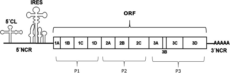
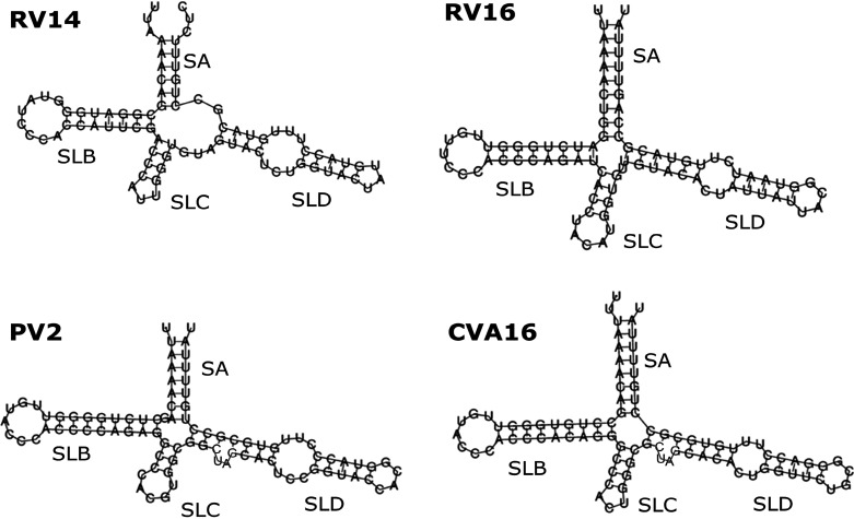
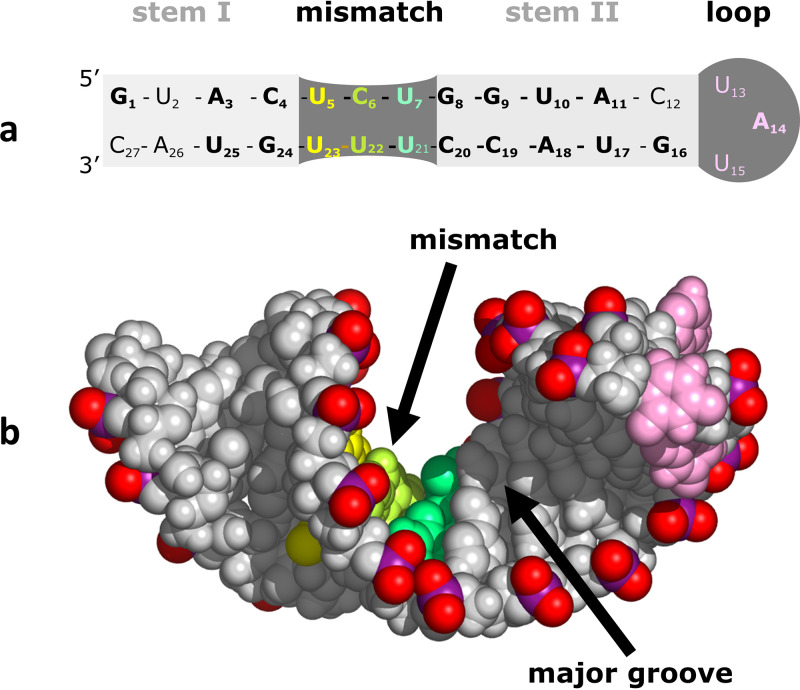
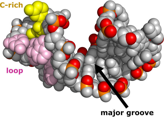
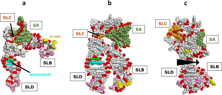
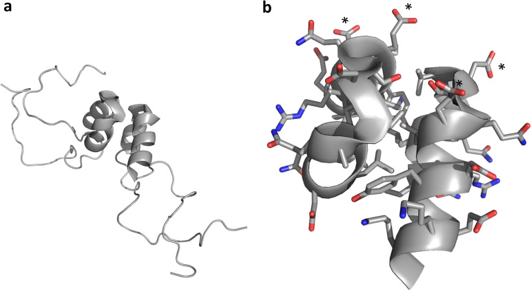
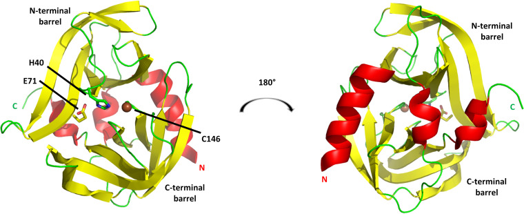
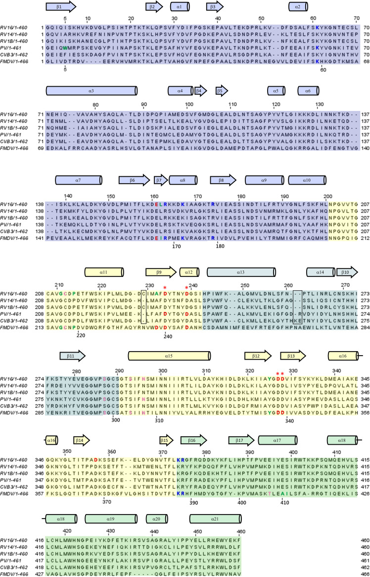
Although enteroviruses are associated with a wide variety of diseases and conditions, their mode of replication is well conserved. Their genome is carried as a single, positive-sense RNA strand. At the 5' end of the strand is an approximately 90-nucleotide self-complementary region called the 5' cloverleaf, or the oriL. This noncoding region serves as a platform upon which host and virus proteins, including the 3B, 3C, and 3D virus proteins, assemble in order to initiate replication of a negative-sense RNA strand. The negative strand in turn serves as a template for synthesis of multiple positive-sense RNA strands. Building on structural studies of individual RNA stem-loops, the structure of the intact 5' cloverleaf from rhinovirus has recently been determined via nuclear magnetic resonance/small-angle X-ray scattering (NMR/SAXS)-based methods, while structures have also been determined for enterovirus 3A, 3B, 3C, and 3D proteins. Analysis of these structures, together with structural and modeling studies of interactions between host and virus proteins and RNA, has begun to provide insight into the enterovirus replication mechanism and the potential to inhibit replication by blocking these interactions.

Keywords: SAXS; X-ray crystallography; enterovirus; nuclear magnetic resonance; picornavirus; structure; viral replication.


Figures

FIG 1
FIG 1
Schematic representation of the enterovirus genome. The 5′ NCR includes a small (<100 nucleotide) cloverleaf that serves as an RNA replication platform and a larger IRES region that controls translation of virus proteins. The single open reading frame (ORF) codes for a single polyprotein that is later separated into 11 proteins (1A through 3D) via the action of virus-encoded proteases. This review focuses upon structural studies of the 5′-cloverleaf (5′-CL) replication platform and the four replication-linked proteins found in region P3 of the polygene (3A, 3B, 3C, and 3D).
FIG 2
FIG 2
Enterovirus 5′-CL predicted secondary structure. The 5′-most 83 nucleotides of the RV14 genome are predicted to form a cloverleaf with a four-way junction. The four converging structural elements are stem A (SA) and stem-loops B, C, and D (SLB, SLC, and SLD). SLB and SLD together comprise over 60% of the cloverleaf. SLD was predicted to contain a 3-by-3 U-rich bulge separating two short Watson-Crick base-paired regions. For comparison, the predicted secondary structure of three of the other enteroviruses discussed in this review are also presented. Note that in these four structures, the string of three cytosines in SLB are conserved, and two of the three pyrimidine mismatches within SLD are also conserved. The predicted lengths of the helices vary, but it appears as if the lengths of SLB and SLD may be correlated.
FIG 3
FIG 3
RV14 SLD structure. (a) Secondary structure derived via NMR structural analysis. Nucleotides conserved between RV14, enterovirus consensus, and CVB3 SLD sequences are shown in bold. These include the mismatch region and 2 bp to the left and 4 bp to the right of the mismatch. The mismatch region is base paired, resulting in a single continuous stem spanning the regions labeled as stem I, mismatch, and stem II. (b) NMR-based structure. Due to strains apparently introduced by mismatch base pair formation, the helix departs from standard A-form geometry and presents a wide and accessible major groove.
FIG 4
FIG 4
RV14 SLB structure. A 6-bp A-form helix is capped by a highly dynamic 8-bp loop (pink and yellow bases), with a C-rich patch (yellow bases) in the loop near the stem. This C-rich region would be accessible to the host poly(C) binding protein (PCBP2). Due to the limited length of the helix, the major groove is accessible.
FIG 5
FIG 5
RV14 5′-CL NMR/SAXS-based structure. (a) Open conformation observed in the absence of magnesium. SLB and SLD are approximately at a right angle to each other. SLC is obscured by stem A (SA) in this view. The positions of the three SLD mismatch base pairs and the SLB C-rich loop region are indicated. (b) Closed conformation observed in the presence of magnesium. SLB and SLD are parallel and in close contact, facilitated by a magnesium counter ion(s); SLC is again obscured. (c) Closed conformation from panel b, rotated 90° to show that the accessible major grooves of SLB and SLD align to create an extensive accessible major groove surface (arrow). SLB is largely obscured by SLD in this view.
FIG 6
FIG 6
3A-N structure. (a) A soluble N-terminal 59-residue fragment of the PV1 3A protein forms a symmetric homodimer in solution. Each monomer contains a helical hairpin, flanked by largely disordered N and C termini. (b) Zoomed view of the 3A-N dimer interface, showing a hydrophobic dimerization surface that includes residues I-22, L-25, L-26, V-29, V-34, Y-37, C-38, and W-43. The nondimer surfaces are highly charged, with a negative charge cluster (D-29 and E-32 from each monomer) indicated by asterisks. Side chain oxygen atoms are shown in red. Side chain nitrogen atoms are shown in blue.
FIG 7
FIG 7
3Cpro from RV14. The cysteine protease structure consists principally of two six-stranded beta barrels connected by a long linker. (Left) View of the proteolytic active-site face, with the position of the three catalytic triad residues indicated. (Right) View of the opposite face, a surface that consists largely of three helices: a long alpha helix at the N terminus (marked by N), a short 310 helix near the C terminus (marked by C), and a short alpha helix at the center of the linker connecting the N-terminal and C-terminal barrels. This opposite face interacts with RNA and phosphoinositides. Models are colored according to secondary structure: helices are red, beta strands are yellow, and other elements are green. The catalytic C-146 sulfur atom is shown as a brown sphere.
FIG 8
FIG 8
Sequence alignment of the 3Dpol variants discussed in this review. The f1 and f2 regions of the fingers domain are shaded blue and teal, respectively. The palm and thumb domains are shaded yellow and green, respectively. Residues discussed in the text are indicated by text coloring according to the polarity of their side chains: red for acidic, blue for basic, pink for polar, and green for hydrophobic. The four conserved Asp residues from the palm domain that are most prominently discussed in the text are marked by red asterisks. Secondary structure is depicted as helices (cylinders) and beta strands (block arrows). Residue numbering above each row of the alignment corresponds to that of RV16. FMDV numbering is provided along the bottom of each row in areas near residues that are discussed in the text. The two boxed regions indicate the regions where the enterovirus sequences contain differing numbers of residues. The positions of these minor gaps can vary slightly in different alignments, but these two small regions account for the minor difference in numbering between the depicted enteroviruses. FMDV is not an enterovirus and has multiple insertions and deletions relative to sequences of the enteroviruses, resulting in larger differences in numbering.
FIG 9
FIG 9
3Dpol from RV16. The structure resembles a right hand (facing the reader), with a central palm domain (yellow) connected to an N-terminal fingers domain (blue and teal) and a C-terminal thumb domain (green). The fingers and thumb are in spatial contact, closing the circle and forming a channel through the polymerase. Side chains of Asp and Asn residues that coordinate catalytically required magnesium ions are shown as red sticks along the top of the palm domain. D-239 also hydrogen bonds to the 2′ OH group of the template, helping to select for an RNA template. The two f2 labels identify residues 243 to 290 (teal) of the fingers domain, which are sequentially inserted between two regions of the palm domain. The five-strand beta sheet from the fingers domain lies below the top f2 label. The positions of the N and C termini are indicated.
FIG 10
FIG 10
3CD from poliovirus. Orientation showing the linker between the 3C and 3D domains, emphasizing that the 3C (left) and 3D (right) domains within a 3CD molecule do not contact each other in the 3CD crystal. The 3C domain makes the closest approach to the N-terminal fingers region of 3D, to which it is covalently attached via the linker. As discussed in the text, in solution, the relative positioning and interactions of the 3C and 3D moieties are dynamic. Coloring is as described in the legends of Fig. 7 and 9, except that no side chains are shown and the linker between 3C and 3D is shown in green.
FIG 11
FIG 11
RV14 3Cpro/SLD complex. 3Cpro is shown as a cartoon and oriented and colored as described in the legend of Fig. 7 (right panel). SLD is shown as spheres. The SLD triloop is shaded darker than the stem regions. The structure indicates that the SLD triloop inserts into 3Cpro between the linker joining the two beta barrels and the N-terminal alpha helix. Broadening of NMR resonances from the N-terminal helix suggests that it may swing into the accessible major groove of SLD (red arrow).
FIG 12
FIG 12
FMDV 3Dpol/RNA elongation complex. (a) The view of 3Dpol is rotated 180° from the view shown in Fig. 9. The RNA template strand (orange) and primer strand (pink) are shown as sticks, while the protein is shown as a cartoon colored as described in the legend of Fig. 9. The 3Dpol structure largely resembles that of RV14 shown in Fig. 9. The FMDV 3Dpol structure was determined in the presence and absence of RNA, and little structural rearrangement was detected. The template RNA strand interacts mainly with the fingers region, while the primer strand interacts with the thumb and palm. A magnesium ion that binds near the catalytic site is shown as a gray sphere, with side chains of the coordinating D-238 and D-240 residues shown as red sticks. The positions of the two catalytic Asp residues, D-338 and D-339, are also indicated by the red loop to the right of the magnesium ion. (b) This view of the structure is rotated 90°. From this side view, it can be seen that the RNA double helix is positioned close to the right-hand surface, which is the top surface of the structure shown in panel a. During replication, new bases would be added to the 3′ end of the primer strand, extending that strand to the left. Thus, the double helix would need to proceed to the right (or, relatively speaking, the polymerase proceeds to the left) in order to processively position the new RNA 3′ end in the polymerase active site.
FIG 13
FIG 13
Poliovirus 3Dpol/RNA elongation complex. (a) The lengthening RNA double helix protrudes from the right side of the polymerase. Orientation and coloring are as shown Fig. 12b. (b) Zoomed image of the active site in its closed conformation. The incoming rNTP (C) and its paired template base (not shown) swing down, displacing D-238, which frees up N-297 and positions S-288 so that both residues hydrogen bond (dashed lines) to the 2′ OH group of the incoming rNTP. In addition, a three-strand beta sheet (upper right) is stabilized, positioning D-233 to coordinate both catalytic magnesium ions (spheres). One of the magnesium ions stabilizes the leaving pyrophosphate group (PP).
FIG 14
FIG 14
3D/VPg initiation complexes. VPg can bind at three different positions. (a) FMDV 3Dpol (cartoon), with VPg1 (sticks) bound in the central cavity. (b) Same structure as shown in panel a but rotated to show that VPg1 extended completely through the cavity. (c) CVB3 3Dpol with VPg bound to the outside of the thumb/palm junction region. (d) EV71 3Dpol with VPg bound to the outside of the palm.

References

    1. Kitamura N, Adler C, Wimmer E. 1980. Structure and expression of the picornavirus genome. Ann N Y Acad Sci 354:183–201. doi:10.1111/j.1749-6632.1980.tb27967.x. - DOI - PubMed
    1. Agol VI. 1980. Structure, translation, and replication of picornaviral genomes. Prog Med Virol 26:119–157. - PubMed
    1. Wimmer E, Kuhn RJ, Pincus S, Yang CF, Toyoda H, Nicklin MJ, Takeda N. 1987. Molecular events leading to picornavirus genome replication. J Cell Sci Suppl 7:251–276. doi:10.1242/jcs.1987.supplement_7.18. - DOI - PubMed
    1. Skern T, Duechler M, Sommergruber W, Blaas D, Kuechler E. 1987. The molecular biology of human rhinoviruses. Biochem Soc Symp 53:63–73. - PubMed
    1. Trono D, Andino R, Baltimore D. 1988. An RNA sequence of hundreds of nucleotides at the 5’ end of poliovirus RNA is involved in allowing viral protein synthesis. J Virol 62:2291–2299. doi:10.1128/JVI.62.7.2291-2299.1988. - DOI - PMC - PubMed

LinkOut - more resources