

Rebound of self-lubricating compound drops
- PMID: 32201721
- PMCID: PMC7069704
- DOI: 10.1126/sciadv.aay3499
Rebound of self-lubricating compound drops
Abstract
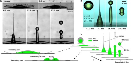
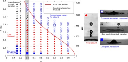
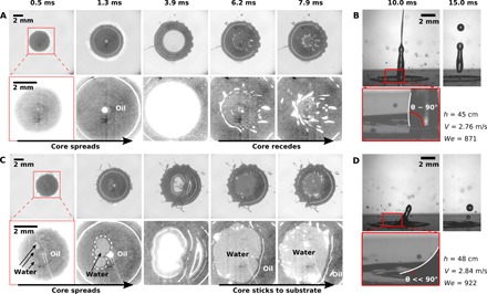
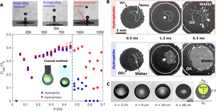
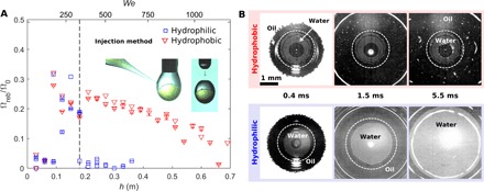
Drop impact on solid surfaces is encountered in numerous natural and technological processes. Although the impact of single-phase drops has been widely explored, the impact of compound drops has received little attention. Here, we demonstrate a self-lubrication mechanism for water-in-oil compound drops impacting on a solid surface. Unexpectedly, the core water drop rebounds from the surface below a threshold impact velocity, irrespective of the substrate wettability. This is interpreted as the result of lubrication from the oil shell that prevents contact between the water core and the solid surface. We combine side and bottom view high-speed imaging to demonstrate the correlation between the water core rebound and the oil layer stability. A theoretical model is developed to explain the observed effect of compound drop geometry. This work sets the ground for precise complex drop deposition, with a strong impact on two- and three-dimensional printing technologies and liquid separation.
Copyright © 2020 The Authors, some rights reserved; exclusive licensee American Association for the Advancement of Science. No claim to original U.S. Government Works. Distributed under a Creative Commons Attribution License 4.0 (CC BY).
Figures
Similar articles
-
Surfactant solutions and porous substrates: spreading and imbibition.Adv Colloid Interface Sci. 2004 Nov 29;111(1-2):3-27. doi: 10.1016/j.cis.2004.07.007. Adv Colloid Interface Sci. 2004. PMID: 15571660
-
Mobility of Aqueous and Binary Mixture Drops on Lubricating Fluid-Coated Slippery Surfaces.Langmuir. 2019 Jun 18;35(24):7672-7679. doi: 10.1021/acs.langmuir.9b00483. Epub 2019 May 29. Langmuir. 2019. PMID: 31117726
-
Receding Phase and Rebound Behavior for Drop Impact onto an Ultrathin Film.Langmuir. 2021 Apr 6;37(13):3849-3857. doi: 10.1021/acs.langmuir.0c03374. Epub 2021 Mar 24. Langmuir. 2021. PMID: 33760612
-
Solid-liquid-liquid wettability and its prediction with surface free energy models.Adv Colloid Interface Sci. 2019 Feb;264:28-46. doi: 10.1016/j.cis.2018.10.003. Epub 2018 Oct 25. Adv Colloid Interface Sci. 2019. PMID: 30396508 Review.
-
Ink-Drop Dynamics on Chemically Modified Surfaces.Langmuir. 2022 Dec 20;38(50):15453-15462. doi: 10.1021/acs.langmuir.2c03108. Epub 2022 Dec 11. Langmuir. 2022. PMID: 36502385 Review.
Cited by
-
Dynamics of an impacting emulsion droplet.Sci Adv. 2022 Mar 18;8(11):eabl7160. doi: 10.1126/sciadv.abl7160. Epub 2022 Mar 18. Sci Adv. 2022. PMID: 35302841 Free PMC article.
-
Liquid metal droplets bouncing higher on thicker water layer.Nat Commun. 2023 Jun 14;14(1):3532. doi: 10.1038/s41467-023-39348-x. Nat Commun. 2023. PMID: 37316489 Free PMC article.
-
The role of drop shape in impact and splash.Nat Commun. 2021 May 24;12(1):3068. doi: 10.1038/s41467-021-23138-4. Nat Commun. 2021. PMID: 34031397 Free PMC article.
-
Characterizing the Bounce and Separation Dynamics of Janus Drop on Macrotextured Surface.Polymers (Basel). 2022 Jun 8;14(12):2322. doi: 10.3390/polym14122322. Polymers (Basel). 2022. PMID: 35745898 Free PMC article.
-
Slippery damper of an overlay for arresting and manipulating droplets on nonwetting surfaces.Nat Commun. 2021 May 26;12(1):3154. doi: 10.1038/s41467-021-23511-3. Nat Commun. 2021. PMID: 34039984 Free PMC article.
References
-
- Josserand C., Thoroddsen S. T., Drop impact on a solid surface. Annu. Rev. Fluid Mech. 48, 365–391 (2016).
-
- Prunet-Foch B., Legay F., Vignes-Adler M., Delmotte C., Impacting emulsion drop on a steel plate: Influence of the solid substrate. J. Colloid Interface Sci. 199, 151–168 (1998).
-
- Shinjo J., Xia J., Ganippa L. C., Megaritis A., Physics of puffing and microexplosion of emulsion fuel droplets. Phys. Fluids 26, 103302 (2014).
LinkOut - more resources
Full Text Sources
