

Plasmonic ommatidia for lensless compound-eye vision
- PMID: 32242009
- PMCID: PMC7118074
- DOI: 10.1038/s41467-020-15460-0
Plasmonic ommatidia for lensless compound-eye vision
Abstract
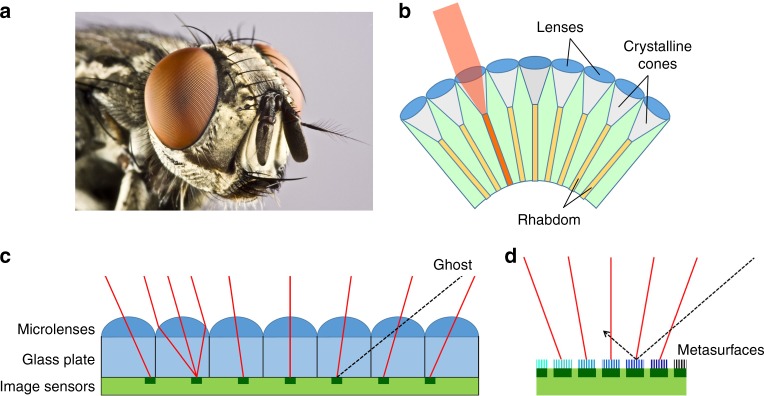
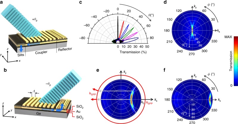
The vision system of arthropods such as insects and crustaceans is based on the compound-eye architecture, consisting of a dense array of individual imaging elements (ommatidia) pointing along different directions. This arrangement is particularly attractive for imaging applications requiring extreme size miniaturization, wide-angle fields of view, and high sensitivity to motion. However, the implementation of cameras directly mimicking the eyes of common arthropods is complicated by their curved geometry. Here, we describe a lensless planar architecture, where each pixel of a standard image-sensor array is coated with an ensemble of metallic plasmonic nanostructures that only transmits light incident along a small geometrically-tunable distribution of angles. A set of near-infrared devices providing directional photodetection peaked at different angles is designed, fabricated, and tested. Computational imaging techniques are then employed to demonstrate the ability of these devices to reconstruct high-quality images of relatively complex objects.
Conflict of interest statement
The authors declare no competing interests.
Figures


Similar articles
-
Gradient-metasurface directional photodetectors.Opt Lett. 2024 Mar 15;49(6):1417-1420. doi: 10.1364/OL.509642. Opt Lett. 2024. PMID: 38489414
-
Optical spatial filtering with plasmonic directional image sensors.Opt Express. 2022 Aug 1;30(16):29074-29087. doi: 10.1364/OE.460556. Opt Express. 2022. PMID: 36299091
-
Fabrication of Artificial Compound Eye with Controllable Field of View and Improved Imaging.ACS Appl Mater Interfaces. 2020 Feb 19;12(7):8870-8878. doi: 10.1021/acsami.9b20740. Epub 2020 Feb 10. ACS Appl Mater Interfaces. 2020. PMID: 32011852
-
Miniature bioinspired artificial compound eyes: microfabrication technologies, photodetection and applications.Front Bioeng Biotechnol. 2024 Feb 16;12:1342120. doi: 10.3389/fbioe.2024.1342120. eCollection 2024. Front Bioeng Biotechnol. 2024. PMID: 38433824 Free PMC article. Review.
-
Artificial Compound Eye Systems and Their Application: A Review.Micromachines (Basel). 2021 Jul 20;12(7):847. doi: 10.3390/mi12070847. Micromachines (Basel). 2021. PMID: 34357257 Free PMC article. Review.
Cited by
-
Adaptive superposition compound eyes for perceptions under distinct light levels.Sci Adv. 2025 Sep 5;11(36):eady2069. doi: 10.1126/sciadv.ady2069. Epub 2025 Sep 5. Sci Adv. 2025. PMID: 40911692 Free PMC article.
-
Bi-stability in femtosecond laser ablation by MHz bursts.Sci Rep. 2024 Mar 7;14(1):5614. doi: 10.1038/s41598-024-54928-7. Sci Rep. 2024. PMID: 38453989 Free PMC article.
-
Metasurface-Coated Liquid Microlens for Super Resolution Imaging.Micromachines (Basel). 2024 Dec 27;16(1):25. doi: 10.3390/mi16010025. Micromachines (Basel). 2024. PMID: 39858681 Free PMC article.
-
A wide-field and high-resolution lensless compound eye microsystem for real-time target motion perception.Microsyst Nanoeng. 2022 Jul 22;8:83. doi: 10.1038/s41378-022-00388-w. eCollection 2022. Microsyst Nanoeng. 2022. PMID: 35874173 Free PMC article.
-
Multilayer all-dielectric metasurfaces expanding color gamut.Nanophotonics. 2024 Jun 26;13(19):3749-3763. doi: 10.1515/nanoph-2024-0258. eCollection 2024 Aug. Nanophotonics. 2024. PMID: 39635036 Free PMC article.
References
-
- Land, M. F. & Nilsson, D. E. Animal Eyes. (Oxford University Press, Oxford, 2002) .
-
- Wu S, et al. Artificial compound eye: a survey of the state-of-the-art. Artif. Intell. Rev. 2017;48:573–603. doi: 10.1007/s10462-016-9513-7. - DOI
Publication types
LinkOut - more resources
Full Text Sources
Other Literature Sources
