Review
. 2020 Mar 31;12(4):759.
doi: 10.3390/polym12040759.

Thermal Welding by the Third Phase Between Polymers: A Review for Ultrasonic Weld Technology Developments

Affiliations
Review

Thermal Welding by the Third Phase Between Polymers: A Review for Ultrasonic Weld Technology Developments

Jianhui Qiu et al. Polymers (Basel). .

Abstract

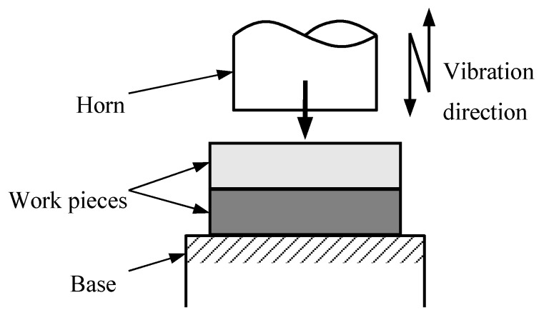
Ultrasonic welding (USW) is a promising method for the welds between dissimilar materials. Ultrasonic thermal welding by the third phase (TWTP) method was proposed in combination with the formation of a third phase, which was confirmed as an effective technology for polymer welding between the two dissimilar materials compared with the traditional USW. This review focused on the advances of applying the ultrasonic TWTP for thermoplastic materials. The research development on the ultrasonic TWTP of polycarbonate (PC) and polymethyl methacrylate (PMMA), polylactic acid (PLA) and polyformaldehyde (POM), and PLA and PMMA are summarized according to the preparation of the third phase, welded strength, morphologies of rupture surfaces, thermal stability, and others. The review aimed at providing guidance for using ultrasonic TWTP in polymers and a basic understanding of the welding mechanism, i.e., interdiffusion and molecular motion mechanisms between the phases.

Keywords: thermal welding by the third phase (TWTP); thermoplastic welding technology; ultrasonic welding (USW); welding between dissimilar materials.


Conflict of interest statement

The authors declare no conflict of interest.

Figures

Figure 1
Figure 1
Schematic illustration of USW method. Adapted from Reference [106].
Figure 2
Figure 2
Conventional USW methods. Adapted from Reference [99].
Figure 3
Figure 3
Schematic drawing of determination of amplitude transmission using a tilted sensor. Adapted from Reference [136].
Figure 4
Figure 4
Power and travel curves as function of energy for the initial weld, produced with a travel of 0.5 mm. Adapted from Reference [142]. (A) intact EDs; (B) collapse of EDs due to melting; (C) partial flow of the EDs and melt-front arrest; (D) remelting of ED melt-fronts and subsequent flow out of the overlap; (E) complete ED squeeze out from the welding interface, with melt and partial flow of the matrix beyond the first adherend layer.
Figure 5
Figure 5
Schematic illustration of joint configuration USW (dimensions in mm). Adapted from Reference [144].
Figure 6
Figure 6
Illustration of polymer using (a) conventional and (b) composite film USW. Adapted from Reference [145].
Figure 7
Figure 7
Welding principle schematic drawing followed by ultrasonic TWTP technology. Adapted from Reference [146,147].
Figure 8
Figure 8
Schematic diagram of IPS preparation for PC-PMMA weld. Adapted from Reference [148].
Figure 9
Figure 9
Nominal stress-strain curves of PC, PMMA, PC/PMMA composite and IPS. Adapted from Reference [149].
Figure 10
Figure 10
Welded strengths at different welding times. (a) Nominal stresses and strain at different welding times under welding pressure of 0.4 MPa; (b) Welded strengths at different welding times. Adapted from Reference [149].
Figure 10
Figure 10
Welded strengths at different welding times. (a) Nominal stresses and strain at different welding times under welding pressure of 0.4 MPa; (b) Welded strengths at different welding times. Adapted from Reference [149].
Figure 11
Figure 11
SEM images of ruptured surfaces of welded interfaces of PC side under welding pressure of 0.3MPa. (a), (b), (c) are under welding time of 1.5 s, 3 s and 4 s. Adapted from Reference [149].
Figure 12
Figure 12
Welded strengths at different welding pressures. (a) Nominal stress and strain at different welding pressures under welding time of 2 s; (b) Welded strengths at different welding pressures under welding times of 2 s and 3 s. Adapted from Reference [149].
Figure 13
Figure 13
SEM images of rupture surfaces under welding time of 3.0 s. (a) and (b) are at welding pressures of 0.1 MPa and 0.4 MPa. Adapted from Reference [149].
Figure 14
Figure 14
TG test of PC, PMMA and PC/PMMA. Adapted from Reference [149].
Figure 15
Figure 15
Welded strengths of PLA and POM at different welding times under welding pressure of 0.4 MPa. Adapted from Reference [150].
Figure 16
Figure 16
Welded strengths at different welding times under welding pressure of 0.3 MPa. Adapted from Reference [150].
Figure 17
Figure 17
Rupture surfaces of welded interface between POM and PLA under welding pressure of 0.4 MPa. (a) is POM side at welding time of 1 s, (b) is PLA side at welding time of 1 s, (c) is POM side at welding time of 2 s and (d) is PLA side at welding time of 2 s. Adapted from Reference [150].
Figure 18
Figure 18
Tensile strengths of matrices and PLA/PMMA blends. Adapted from Reference [148].
Figure 19
Figure 19
Tensile strengths of matrices and PLA/PMMA blends. Adapted from Reference [148].
Figure 20
Figure 20
TG analysis of PLA, PMMA, and PLA/PMMA blends of 1:1. Adapted from Reference [151].
Figure 21
Figure 21
Welded strengths at different welding times under different welding pressures (P). Adapted from Reference [151].
Figure 22
Figure 22
SEM images of rupture surfaces under welding pressure of 0.3 MPa and welding time of (a) 1 s, (b) 2 s, (c) 3 s and (d) 5 s. Adapted from Reference [151].
Figure 23
Figure 23
Schematic drawing of macromolecular inter-diffusion of IPS and WPs. Adapted from Reference [147]. Temperatures of the interfaces are (a) under room temperature; (b) higher than glass transition temperature; (c) above melting point; (d) back to room temperature.

Similar articles

Cited by

References

    1. Red C. The outlook for thermoplastics in aerospace composites, 2014–2023. High Perform. Compos. 2014;22:54–63.
    1. Ajay K., Jayashree B. Investigations on performance and failure mechanisms of high temperature thermoplastic polymers as adhesives. Int. J. Adhes. Adhes. 2016;70:90–101.
    1. Villegas I.F., Moser L., Yousefpour A., Mitschang P., Bersee H.E.N. Process and performance evaluation of ultrasonic, induction and resistance welding of advanced thermoplastic composites. J. Thermoplast. Compos. 2012;26:1007–1024. doi: 10.1177/0892705712456031. - DOI
    1. Ulisses H.R., Inés F., Elisa V. Ultrasonic Molding Technology: Recent Advances and Potential Applications in the Medical Industry. Polymers. 2019;11:667. - PMC - PubMed
    1. Kellomaki M., Tormala P. Ultrasonic moulding of bioabsorbable polymers and polymer/drug composites. J. Mater. Sci. Lett. 1997;16:1786–1789. doi: 10.1023/A:1018548130539. - DOI

LinkOut - more resources