Review
. 2020 Mar 19:7:1-23.
doi: 10.2147/RSRR.S224446. eCollection 2020.

Robotically Steered Needles: A Survey of Neurosurgical Applications and Technical Innovations

Affiliations
Review

Robotically Steered Needles: A Survey of Neurosurgical Applications and Technical Innovations

Michel A Audette et al. Robot Surg. .

Abstract

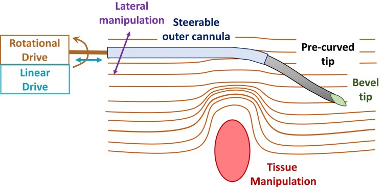
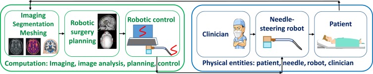
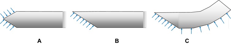
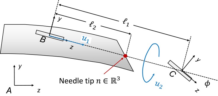
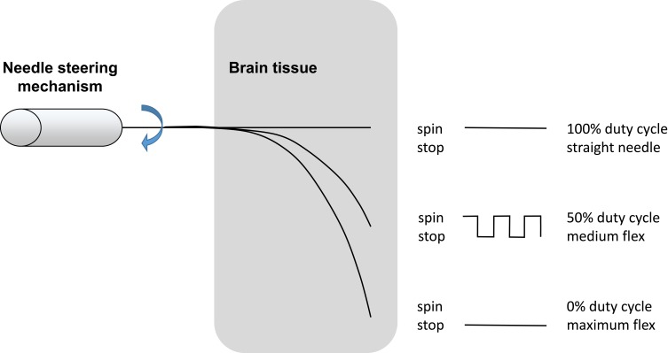
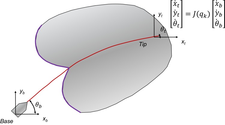
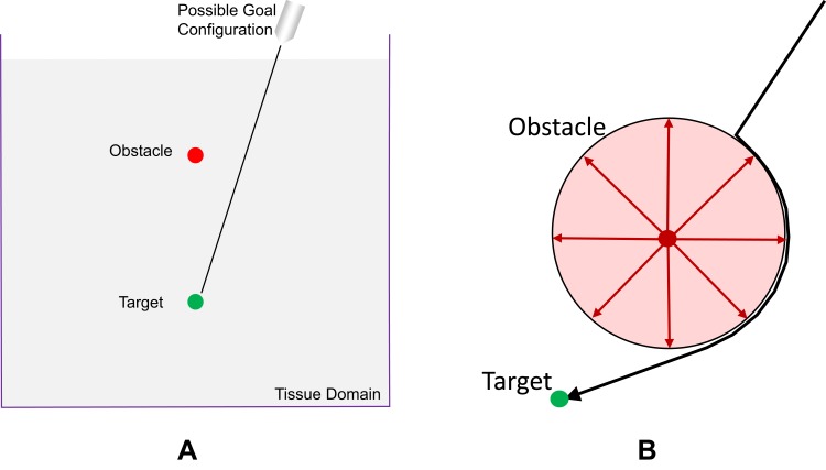
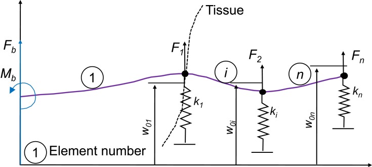
This paper surveys both the clinical applications and main technical innovations related to steered needles, with an emphasis on neurosurgery. Technical innovations generally center on curvilinear robots that can adopt a complex path that circumvents critical structures and eloquent brain tissue. These advances include several needle-steering approaches, which consist of tip-based, lengthwise, base motion-driven, and tissue-centered steering strategies. This paper also describes foundational mathematical models for steering, where potential fields, nonholonomic bicycle-like models, spring models, and stochastic approaches are cited. In addition, practical path planning systems are also addressed, where we cite uncertainty modeling in path planning, intraoperative soft tissue shift estimation through imaging scans acquired during the procedure, and simulation-based prediction. Neurosurgical scenarios tend to emphasize straight needles so far, and span deep-brain stimulation (DBS), stereoelectroencephalography (SEEG), intracerebral drug delivery (IDD), stereotactic brain biopsy (SBB), stereotactic needle aspiration for hematoma, cysts and abscesses, and brachytherapy as well as thermal ablation of brain tumors and seizure-generating regions. We emphasize therapeutic considerations and complications that have been documented in conjunction with these applications.

Keywords: brain biopsy; brachytherapy; deep-brain stimulation; intracerebral drug delivery; needle steering; stereoelectroencephalography; stereotactic needle aspiration.


Conflict of interest statement

The authors report no conflicts of interest in this work.

Figures

Figure 1
Figure 1
Summary of techniques applied to needle steering, emphasizing the asymmetric (eg, bevel) tip, pre-curved needle segments, steerable outer cannula, independent tissue manipulation, lateral manipulation, and positioning based linear or rotational motion, as defined in relation to the needle central axis. Data from Cowan et al.
Figure 2
Figure 2
Basic architecture of needle-steering robotic system. Data from Cowan et al. The left side, depicted in green integrates all computerized components: medical imaging and image analysis, surgery planning and robotic control. Imaging can also occur intraoperatively, leading to anatomy update. The right side depicts physical entities: the surgeon, robot and needle, as well as the patient.
Figure 3
Figure 3
Needle tip shapes featuring (A) a symmetric and cone-shaped tip, (B) an asymmetric beveled tip. (C) Combination of bevel tip and pre-bent needle shape. Data from Cowan et al.
Figure 4
Figure 4
Webster’s nonholonomic model of beveled tip needle emphasizing a pair of bicycle “wheels” at frames B and C. The x coordinate axes for frames (A, B and C) are pointing into the page. Data from Winters et al and Cowan et al.
Figure 5
Figure 5
Relationship between spinning duty cycle of beveled needle and its induced flexion. Data from Engh et al.
Figure 6
Figure 6
Needle manipulation Jacobian model for expressing tip motion in relation to base translation and rotation. Data from DiMaio et al.
Figure 7
Figure 7
DiMaio’s potential field formalism. (A) Tissue-spanning 2D domain with embedded target and obstacle components. A multiplicity of starting and goal positions are feasible. (B) Example of repulsive obstacle: circular repulsion potential. Data from Rucker et al.
Figure 8
Figure 8
Glozman’s beam element and spring model for needle insertion into tissue. Data from DiMaio and Salcudean.
Figure 9
Figure 9
MRI-compatible neurosurgical robotics. (A) NeuroArm MRI-compatible neurosurgery robot, shown with patient in foreground and MRI scanner in the background. Reproduced with permission from NeuroArm. Project. (B) Development of MRI-compatible deep brain stimulation robotic assistant by G.S. Fischer et al Unpublished DBS robot images graciously contributed by G.S. Fischer of Worcester Polytechnic Institute.
Figure 10
Figure 10
Plots of force against displacement, demonstrating the effect of the variation of the ratio of Young’s moduli E2/E1, for simulated needle insertion into simulated soft tissue. Image courtesey of S.P.A. Bordas.
Figure 11
Figure 11
Mathematical modelling process and its pitfalls, with some solutions provided by Validation (Are we solving the right problem?) and Verification (Are we solving the problem right?), which elicits other questions about efficiency and whether an exact solution exists.
Figure 12
Figure 12
Stereotactic needle-based biopsy of large craniopharyngioma cyst in 11-year-old boy. (i) Operating room setup. (A) Anesthetized patient with stereotactic ring affixed to his head prior to the procedure. (B) Probe oriented towards the surgical entry point. (ii) (AD) Surgical planning and navigation for biopsy. The procedure involves puncturing and draining the cyst, based on a visualization oriented according to the needle trajectory. Copyright © 2012. Reproduced from Trippel M, Nikkhah G. Stereotactic neurosurgical treatment options for craniopharyngioma. Front Endocrinol (Lausanne). 2012;3:63.
Figure 13
Figure 13
N-shaped fiducials for frame localization within a medical image. (A) Lateral view of the N-fiducial. Each N-fiducial result in a characteristic intersection with every image plane. (B) Typical intersection of the fiducial with a CT image. This intersection with the fiducial results in a pair of circles and an ellipse. The location of the ellipse between the two circles is a function of the height at which the tomographic image plane intersects the diagonal rod. Copyright © 2006. Wikipedia. Reproduced from uploader. Stereotactic surgery. Available from: https://en.wikipedia.org/wiki/Stereotactic_surgery.
Figure 14
Figure 14
DBS neuroanatomical targets. (A) Nucleus basalis (NB) targeted in Alzheimer’s disease and in Lewy body disease. Copyright © 2015. Reproduced with permission from Zhang Q, Kim Y-C and Narayanan NS. Disease-modifying therapeutic directions for Lewy-Body dementias. Front. Neurosci. 2015;9:293. (B) Thalamus, the anterior nucleus of which is shown in dark blue and targeted for DBS of epilepsy. Copyright © 2011. Wikipedia. Reproduced from uploader. Thalamus-schematic-de.svg.  Available from: https://commons.wikimedia.org/wiki/File:Thalamus-schematic-de.svg. (C) Subthalamic nucleus (STN) and substantia nigra (SN) depicted in coronal plane in yellow and red, respectively. (D) The reward pathway spans several parts of the brain, as highlighted: the ventral tegmentum (labeled VT), nucleus accumbens, as well as the prefrontal cortex. Reproduced with permission. National Institute on Drug Abuse. Public Domain Picture: Brain reward pathway. Available from http://www.publicdomainfiles.com/show_file.php?id=13989816622720.
Figure 15
Figure 15
SEEG surgery planning. (A, B, C) 3D volume renderings of patient brains, with overlaid labels of electrode locations defined in stereotactic space. (D) Axial and coronal planar representations of patient T1-weighted brain image, with electrode paths J and K highlighted. Epileptogenic zones are labeled as J6, J7, K6, and K7. (D) Comparable axial and coronal planes of a co-registered PET volume: green labels correspond to lesser metabolic areas. Copyright © 2018. Reproduced with permission from Wang J, Wang Q, Wang M, et al. Occipital lobe epilepsy with ictal fear: evidence from a stereo-electroencephalography (sEEG) case. Front Neurol. 2018;9:644.
Figure 16
Figure 16
Miniaturized neural drug delivery system (MiNDS). (A) Schematic of system with key components shown in bottom-right inset; and borosilicate aligner tip depicted in top-left inset. (B) Depiction of long and short versions of MiNDS device: L-MiNDS and S-MiNDS, with electrical connection and fluidic channels identified. (C, D) Scanning electron microscopies. (C) SEM view of L-MiNDS tip. (D) SEM view of BS aligner tip. (E) PET images of diffusion of Cu-64 in vivo subsequent to MiNDS-mediated delivery in a rat. Images taken at 5, 10, 15, and 20 mins depict expression of Cu-64. Copyright © 2018. Reproduced with permission from Dagdeviren C, Ramadi KB, Joe P, et al. Miniaturized neural system for chronic, local intracerebral drug delivery. Sci Transl Med. 2018;10(425):eaan2742.
Figure 17
Figure 17
Stereotactic Intracerebral Hemorrhage Underwater Blood Aspiration (SCUBA) technique. (A) The cannula is inserted distally to the hematoma under stereotactic navigation. (B) Blood of the hematoma is aspirated as brain tissue closes in around the tip whereupon the cannula is retracted a few centimeters. (C) Subsequently, the surgeon infuses saline through the cannula, filling the cavity. (D) The saline is evacuated, and the cannula is fully retracted; intraoperative ultrasound and DYNA CT images are acquired to confirm the hematoma removal. Copyright © 2018. BMJ. Reproduced with permission from Kellner CP, Chartrain AG, Nistal DA, et al. The stereotactic intracerebral hemorrhage underwater blood aspiration (SCUBA) technique for minimally invasive endoscopic intracerebral hemorrhage evacuation. J Neurointerv Surg. 2018;10(8):771–776.
Figure 18
Figure 18
NeuroBlate commercial laser-based thermal ablation system for neurosurgical applications. (A) Robotic positioning system, enabling probe positioning from workstation during the procedure. (B) Two optic laser probes available for NeuroBlate: directional and diffusing tip probes.,, Reproduced with permission from Monteris Medical. NeuroBlate® system. [Online] Available from: https://www.monteris.com/neuroblate-system/.

Similar articles

Cited by

References

    1. Perlmutter JS, Mink JW. Deep brain stimulation. Annu Rev Neurosci. 2006;29:229–257. doi:10.1146/annurev.neuro.29.051605.112824 - DOI - PMC - PubMed
    1. Goldstein HE, Youngerman BE, Shao B, et al. Safety and efficacy of stereoelectroencephalography in pediatric focal epilepsy: a single-center experience. J Neurosurg Pediatr. 2018;22(4):444–452. doi:10.3171/2018.5.PEDS1856 - DOI - PubMed
    1. Engh JA, Minhas DS, Kondziolka D, Riviere CN. Percutaneous intracerebral navigation by duty-cycled spinning of flexible bevel-tipped needles. Neurosurgery. 2010;67(4):1117–1122. doi:10.1227/NEU.0b013e3181ec1551 - DOI - PubMed
    1. Chandrasoma PT, Smith MM, Apuzzo ML. Stereotactic biopsy in the diagnosis of brain masses: comparison of results of biopsy and resected surgical specimen. Neurosurgery. 1989;24(2):160–165. doi:10.1227/00006123-198902000-00002 - DOI - PubMed
    1. Chen L, Dong L, She L, et al. Treatment of chronic subdural hematoma by novel YL-1 hollow needle aspiration drainage system (697 cases report). Neurol Sci. 2017;38(1):109–113. doi:10.1007/s10072-016-2717-4 - DOI - PubMed