

INS-fOCT: a label-free, all-optical method for simultaneously manipulating and mapping brain function
- PMID: 32258220
- PMCID: PMC7108754
- DOI: 10.1117/1.NPh.7.1.015014
INS-fOCT: a label-free, all-optical method for simultaneously manipulating and mapping brain function
Abstract
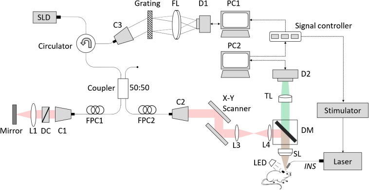
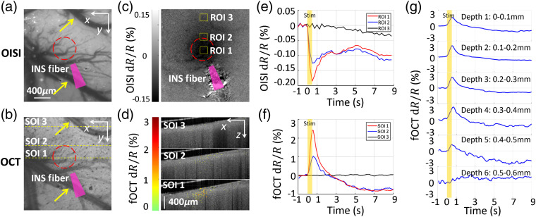
Significance: Current approaches to stimulating and recording from the brain have combined electrical or optogenetic stimulation with recording approaches, such as two-photon, electrophysiology (EP), and optical intrinsic signal imaging (OISI). However, we lack a label-free, all-optical approach with high spatial and temporal resolution. Aim: To develop a label-free, all-optical method that simultaneously manipulates and images brain function using pulsed near-infrared light (INS) and functional optical coherence tomography (fOCT), respectively. Approach: We built a coregistered INS, fOCT, and OISI system. OISI and EP recordings were employed to validate the fOCT signals. Results: The fOCT signal was reliable and regional, and the area of fOCT signal corresponded with the INS-activated region. The fOCT signal was in synchrony with the INS onset time with a delay of . The magnitude of fOCT signal exhibited a linear correlation with the INS radiant exposure. The significant correlation between the fOCT signal and INS was further supported by OISI and EP recordings. Conclusions: The proposed fiber-based, all-optical INS-fOCT method allows simultaneous stimulation and mapping without the risk of interchannel cross-talk and the requirement of contrast injection and viral transfection and offers a deep penetration depth and high resolution.
Keywords: functional imaging; functional optical coherence tomography; infrared neural stimulation.
© The Authors. Published by SPIE under a Creative Commons Attribution 4.0 Unported License. Distribution or reproduction of this work in whole or in part requires full attribution of the original publication, including its DOI.
Figures


Similar articles
-
Functional optical coherence tomography of rat olfactory bulb with periodic odor stimulation.Biomed Opt Express. 2016 Feb 10;7(3):841-54. doi: 10.1364/BOE.7.000841. eCollection 2016 Mar 1. Biomed Opt Express. 2016. PMID: 27231593 Free PMC article.
-
Novel functional imaging technique from brain surface with optical coherence tomography enabling visualization of depth resolved functional structure in vivo.J Neurosci Methods. 2003 Mar 30;124(1):83-92. doi: 10.1016/s0165-0270(02)00370-9. J Neurosci Methods. 2003. PMID: 12648767
-
Functional optical coherence tomography reveals localized layer-specific activations in cat primary visual cortex in vivo.Opt Lett. 2007 Sep 1;32(17):2614-6. doi: 10.1364/ol.32.002614. Opt Lett. 2007. PMID: 17767323
-
In-vivo Optical Measurement of Neural Activity in the Brain.Exp Neurobiol. 2013 Sep;22(3):158-66. doi: 10.5607/en.2013.22.3.158. Epub 2013 Sep 30. Exp Neurobiol. 2013. PMID: 24167411 Free PMC article. Review.
-
Acute damage threshold for infrared neural stimulation of the cochlea: functional and histological evaluation.Anat Rec (Hoboken). 2012 Nov;295(11):1987-99. doi: 10.1002/ar.22583. Epub 2012 Oct 8. Anat Rec (Hoboken). 2012. PMID: 23044730 Free PMC article. Review.
Cited by
-
Exploring the structure, metabolism, and biochemistry of the neuronal microenvironment label-free using fast simultaneous multimodal optical microscopy.Optica. 2024 Sep 20;11(9):1352-1367. doi: 10.1364/optica.532367. Epub 2024 Sep 19. Optica. 2024. PMID: 40476225
-
Ultra-parallel label-free optophysiology of neural activity.iScience. 2022 Apr 27;25(5):104307. doi: 10.1016/j.isci.2022.104307. eCollection 2022 May 20. iScience. 2022. PMID: 35602935 Free PMC article.
-
Single infrared light pulses induce excitatory and inhibitory neuromodulation.Biomed Opt Express. 2021 Dec 16;13(1):374-388. doi: 10.1364/BOE.444577. eCollection 2022 Jan 1. Biomed Opt Express. 2021. PMID: 35154878 Free PMC article.
