Review
. 2020 Apr 4;12(4):818.
doi: 10.3390/polym12040818.

Application of the Finite Element Method in the Analysis of Composite Materials: A Review

Affiliations
Review

Application of the Finite Element Method in the Analysis of Composite Materials: A Review

Sarah David Müzel et al. Polymers (Basel). .

Abstract

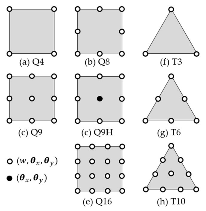
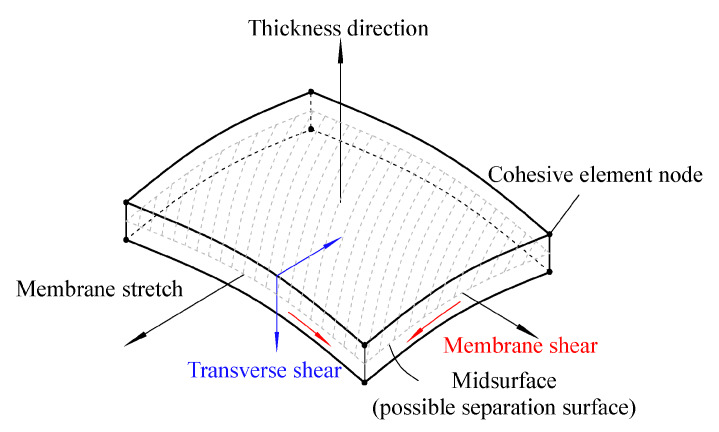
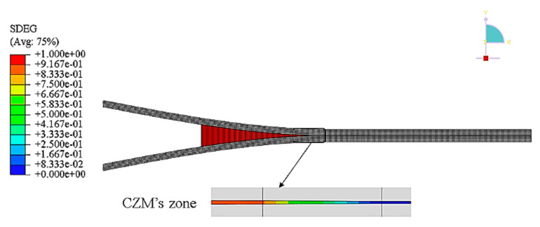
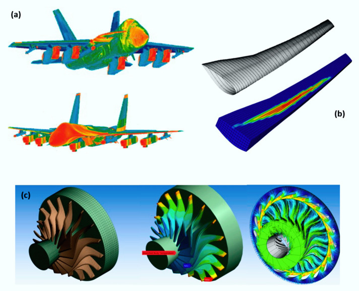
The use of composite materials in several sectors, such as aeronautics and automotive, has been gaining distinction in recent years. However, due to their high costs, as well as unique characteristics, consequences of their heterogeneity, they present challenging gaps to be studied. As a result, the finite element method has been used as a way to analyze composite materials subjected to the most distinctive situations. Therefore, this work aims to approach the modeling of composite materials, focusing on material properties, failure criteria, types of elements and main application sectors. From the modeling point of view, different levels of modeling-micro, meso and macro, are presented. Regarding properties, different mechanical characteristics, theories and constitutive relationships involved to model these materials are presented. The text also discusses the types of elements most commonly used to simulate composites, which are solids, peel, plate and cohesive, as well as the various failure criteria developed and used for the simulation of these materials. In addition, the present article lists the main industrial sectors in which composite material simulation is used, and their gains from it, including aeronautics, aerospace, automotive, naval, energy, civil, sports, manufacturing and even electronics.

Keywords: anisotropic material; failure criteria; multiscale approaches; orthotropic material; plate element; shell element; transverse isotropic material.


Conflict of interest statement

The authors declare no conflict of interest.

Figures

Figure 1
Figure 1
Scheme of the most common uses of fiber reinforced composite structures: (a) unidirectional fiber orientation ply, (b) bidirectional fiber orientation ply (woven-ply) and (c) multiorientation laminate, quasi-isotropic laying-up sequence [0°/45°/90°/−45°] 6S. Reproduced with permission [13].
Figure 2
Figure 2
Schematic view of the fiber, matrix and equivalent homogeneous material (EHM) domains used in a finite element model for the case of 45° fiber orientation. Reproduced with permission [30].
Figure 3
Figure 3
From the microscale to the macroscale. Reproduced with permission [33].
Figure 4
Figure 4
Schematic view of a four-scale woven fiber composite with polymer matrix: In computational modeling of this structure, each integration point at any scale is a realization of a structure at a finer scale. Due to the delicacy of materials at fine-scales, RVEs at lower scales may embody more uncertainty than those at higher scales. To quantify the uncertainty in a macroscopic quantity of interest, the relevant uncertainty sources at the lower scales should be identified for uncertainty propagation. Reproduced with permission [41].
Figure 5
Figure 5
Schematic of multiscale modelling of engineering composite structures. Reproduced with permission [46].
Figure 6
Figure 6
Hierarchy of multiscale analysis for a unidirectional fiber reinforced composite.
Figure 7
Figure 7
Multiscale analysis hierarchy for a two-way fiber reinforced composite.
Figure 8
Figure 8
(a) Square arrangement of the microscale unit cell and (b) mesoscale, macroscopic unit cell.
Figure 9
Figure 9
Multiscale modelling strategy for woven composite laminates.
Figure 10
Figure 10
The sketch for the fiber architectures in the 3D model, (a) overall spatial view, (b) top vie, (c) side view, and (d) a fiber is described by the center point C, and two Euler angles θ and φ. Reproduced with permission [50].
Figure 11
Figure 11
Cohesive zone model to simulate crack propagation.
Figure 12
Figure 12
Schematic damage process zone and corresponding bi-linear traction–separation law in an adhesively bonded joint. Reproduced with permission [67].
Figure 13
Figure 13
Basic strength parameters of unidirectional lamina for in-plane loading, (a) longitudinal tensile, (b) longitudinal compressive, (c) transverse tensile, (d) transverse compressive, and (e) in-plane or interlaminar shear.
Figure 14
Figure 14
Comparison of theoretical and experimental results. Reproduced with permission [191].
Figure 15
Figure 15
Progressive failure analysis with Hashin failure criteria for 45° fiber orientation. (a) Fiber–matrix interface detachment, (b) matrix fracture and (c) fiber rupture. Reproduced with permission [24].
Figure 16
Figure 16
(a) Section of plate of thickness t, under transverse loading q¯ per unit area, where w is a transverse displacement of a point of the mean surface, and θx and θy are the rotations normal to the same point according to the x and y axes. Reproduced with permission [75]. (b) Field of displacements according to Kirchhoff’s plate theory. Reproduced with permission [212].
Figure 17
Figure 17
Rectangular plate element by Kirchhoff’s theory.
Figure 18
Figure 18
Non-conforming triangular elements. Reproduced with permission [75].
Figure 19
Figure 19
Compliant thin-plate elements. Reproduced with permission [75].
Figure 20
Figure 20
Field of displacements according to Reissner–Mindlin plate theory Reproduced with permission [212].
Figure 21
Figure 21
Finite elements based on the Reissner–Mindlin theory.
Figure 22
Figure 22
(a) 20-node isoparametric solid element; (b) reduction to eight nodes using a shell element; and (c) b-node representation.
Figure 23
Figure 23
(a) Free body diagram for the equilibrium of in-plane forces and (b) free body diagram for the equilibrium of transverse shear forces.
Figure 24
Figure 24
(a) Association of elements and (b) degenerate shell.
Figure 25
Figure 25
Triangle element in xy plane. Reproduced with permission [75].
Figure 26
Figure 26
Curved element. Reproduced with permission [75].
Figure 27
Figure 27
Asymmetric shell element. Reproduced with permission [75].
Figure 28
Figure 28
Interface element analysis of delamination in a double cantilever beam. Reproduced with permission [64].
Figure 29
Figure 29
Progressive failure process of the adhesive layer in the lap-shear joint, (a) damage initiation at the overlap edges (SDEG-% = 0), (b) propagation towards the joint centre (SDEG-% ≈ 40), (c) joint failure (SDEG-% = 100). Reproduced with Creative Common License [239].
Figure 30
Figure 30
Spatial representation of CH3D8 (eight-node three-dimensional) cohesive element. Reproduced with Creative Common License [240].
Figure 31
Figure 31
Typical application involving gaskets, (a) Reproduced with permission [241] and (b) Reproduced with permission [242].
Figure 32
Figure 32
Damage of cohesive elements in the wake of delamination front. Reproduced with permission [246].
Figure 33
Figure 33
Typical traction separation laws according to: (a) Needleman 1987, (b) Needleman 1990, (c) Hillerborg 1976, (d) Bazant 2002, (e) Scheider and Brocks 2003, (f) Tvergaard and Hutchinson 1992.
Figure 34
Figure 34
Typical traction–separation response. Reproduced with Creative Common License [249].
Figure 35
Figure 35
Cohesive element nodes and integration point positions, and connecting cohesive and continuum elements.
Figure 36
Figure 36
Cohesive element (a) plane stress/strain models and (b) shell models.
Figure 37
Figure 37
Some fields of FEM’s application to composites: (a) wind power, (b) sports, (c) automotive, (d) construction, (e) naval. Reproduced with Creative Common License [267], (f) aeronautics. Reproduced with permission [268] and (g) space. Reproduced with Creative Common License [269] industries.
Figure 38
Figure 38
Use of composite materials in aircraft over the years.
Figure 39
Figure 39
Some applications of FEM in composites in the aeronautical industry: (a) fluid–structure. Reproduced with Creative Common License [288], (b) wing geometry. Reproduced with permission [289] and (c) tube rotor blade improvement. Reproduced with Creative Common License [290].
Figure 40
Figure 40
Some applications of FEM in composites in the space sector: (a) satellite. Reproduced with Creative Common License [269], and (b) coupled launcher–satellite structure. Reproduced with permission [295].
Figure 41
Figure 41
Some applications of FEM in composites in the automotive sector: (a) impact. Reproduced with Creative Common License [266], and (b) car racing.
Figure 42
Figure 42
Some applications of FEM in composites in the naval sector: (a) propellers. Reproduced with permission [303], (b) submarines. Reproduced with Creative Common License [267] and (c) ships.
Figure 43
Figure 43
Some applications of FEM in composites for the energy sector: (a) wind turbines. Reproduced with permission [310] and (b) pipes for the oil and gas industry.
Figure 44
Figure 44
Some applications of FEM for composites in construction: (a) Strengthening flexural solid timber beams with CFRP. Reproduced with permission [323] and (b) bridges.
Figure 45
Figure 45
Some applications of FEM for composites in the sport sector: (a) a tennis racket, (b) a bicycle and (c) a prosthetic. Reproduced with Creative Common License [331].
Figure 46
Figure 46
Example of damage cause by machining, (a) Reproduced with Creative Common License [333] and (b) Reproduced with permission [334].
Figure 47
Figure 47
(a) Damage occurred in the FEM (left) and in the mechanical test (right). (b) Digital Image Correlation with overlapped shear strain (above) and FE damage (below) for the OHT coupon at 1,000,000 cycles. Reproduced with permission [338].

References

    1. Rezende M.C., Costa M.L., Botelho E.C. Compósitos Estruturais: Tecnologia e Prática. 1st ed. Artliber; São Paulo, Brazil: 2011.
    1. Callister Junior W.D., Rethwisch D.G. Materials Science and Engineering: An. Introduction. 8th ed. LTC; São Paulo, Brazil: 2013.
    1. Kaw A.K. Mechanics of Composite Materials. 2nd ed. Taylor & Francis; Boca Raton, FL, USA: 2006.
    1. Durand L.P., editor. Composite Materials Research Progress. 1st ed. Nova Science Publishers, Inc.; New York, NY, USA: 2008.
    1. Chung D.D.L. Engineering Materials and Processes. 2nd ed. Springer; London, UK: 2010. Composite Materials.