. 2020 May 13;20(5):3611-3619.
doi: 10.1021/acs.nanolett.0c00556. Epub 2020 Apr 21.

Diamond-Graphene Composite Nanostructures

Affiliations

Diamond-Graphene Composite Nanostructures

Péter Németh et al. Nano Lett. .

Abstract

The search for new nanostructural topologies composed of elemental carbon is driven by technological opportunities as well as the need to understand the structure and evolution of carbon materials formed by planetary shock impact events and in laboratory syntheses. We describe two new families of diamond-graphene (diaphite) phases constructed from layered and bonded sp3 and sp2 nanostructural units and provide a framework for classifying the members of this new class of materials. The nanocomposite structures are identified within both natural impact diamonds and laboratory-shocked samples and possess diffraction features that have previously been assigned to lonsdaleite and postgraphite phases. The diaphite nanocomposites represent a new class of high-performance carbon materials that are predicted to combine the superhard qualities of diamond with high fracture toughness and ductility enabled by the graphitic units and the atomically defined interfaces between the sp3- and sp2-bonded nanodomains.

Keywords: Graphene-diamond nanocomposite; density functional theory calculations; high-resolution TEM; mechanical properties; sp2- and sp3-bonded nanomaterials.


Conflict of interest statement

The authors declare no competing financial interest.

Figures

Figure 1
Figure 1
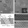
HRTEM images and EELS data showing the existence of type 1 diaphite nanocomposites resulting from few-layered graphene units inserted within {111} diamond. (a) HRTEM image of a graphene-diamond particle from the shocked Gujba meteorite (adapted with permission from ref (27), Figure 5b. Copyright 2014 Mineralogical Society of America). White and black lines mark crystallographically related ∼3.4 Å {00l} graphene and ∼2.1 Å {111} diamond spacings, respectively. The FFTs in the inset to this and other TEM images show the characteristic graphene (marked by white circles) and ⟨011⟩ diamond reflections. (b) DFT-calculated structure model of type 1 diaphite for the area marked by white corners of (a). The model shows the Pandey (2 × 1) reconstructed surfaces of the bottom and top {111} diamond layers (marked by dotted lines), the arrangement of which is unresolved on the experimental image. (c) Background-filtered image (unprocessed image shown in Figure S1a) of an interfingering graphene-diamond nanocomposite observed within a Popigai diamond. (d) Overlapping graphene-diamond nanocomposites from a 1.5 Mbar laboratory-shocked graphite sample show continuous 2.06 Å (diamond) and 3.4 Å (graphene) fringes. Although the superposition of graphene and diamond units of type 1 diaphite makes the exact determination of individual components challenging, the FFT shows the characteristic diffraction features of type 1 diaphite. (e) EELS data for selected graphene-diamond nanocomposite regions (shown in Figure S2) from a Popigai diamond indicate mixed sp2 (graphitic) and sp3 (diamond) bonding.
Figure 2
Figure 2
HRTEM images and DFT modeling of a type 2 diaphite nanocomposite containing graphitic layers inserted at high angles within {113} diamond. (a) HRTEM image from a Popigai diamond shows perpendicular 2.1 and 1.26 Å (contoured by a black circle) as well as hexagonally arranged 2.1 Å fringes (contoured by a white circle). (b) Background filtered image calculated from the area marked by white corners of (a). The FFT in the inset shows ⟨001⟩ graphene hklg partly overlapping with ⟨121⟩ diamond hkld reflections. (c) Structure model of type 2 diaphite and its characteristic d spacings obtained from DFT calculations. (d) The simulated HRTEM image calculated from the structure shown in (c) using the experimental microscopy conditions successfully reproduces the image contrast of the observed features (e) from the area marked by white corners of (b).
Figure 3
Figure 3
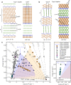
Structural examples of type 1 and 2 diaphite structures and a comparison of DFT calculated energy (E)–volume (V) values for diaphite structures and a range of stable and metastable carbon allotropes. Model structures for the basic type 1 diaphite (a) and type 2 diaphite (b). Their structures are defined in terms of the number of diamond (d) and graphite (g) components. In type 1, d defines the number of {111} diamond layers between Pandey (2 × 1) reconstructed surfaces, and g is the number of {001} graphite layers. Type 1 models can be constructed with d and g independently taking any number between 1 → ∞. In type 2, d is the number of {113} diamond layers, and g is the number of {100} graphite layers between the diamond regions. The constraints imposed by the choice of unit cells require that for type 2 models d + g = 2n, where n is an integer. For both structures, g = 1, d = 1 results in the highest density of interfaces. Structure examples shown are g = 4, d = 9 (type 1) and g = 5, d = 5 (type 2). Green, orange, and blue units correspond to sp2-bonded graphene, sp3-bonded diamond, and sp2- and sp3-bonded atoms in Pandey (2 × 1) reconstruction, respectively. (c) EV plot of type 1 and 2 diaphite and other carbon allotropes. Markers indicate calculated structures. The predicted E–V regions in which type 1 and 2 diaphite structures can appear under ambient conditions are indicated by the shaded regions. Dashed lines indicate estimated pressures as the E(V) slopes that can be attained in static or dynamic compression experiments or shock impacts. The panel in the bottom right expands the region indicated in black brackets in (c). The labels for calculated type 1 and 2 diaphite structures are shown in Figures S5 and S8.
Figure 4
Figure 4
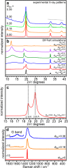
X-ray diffraction and Raman spectroscopy of Popigai diamonds. (a) Experimental X-ray diffraction patterns (MoKα: λ = 0.71073 Å) with different hexagonality indices (ΦDH) as indicated in ref (17). The dashed lines highlight a diffuse diffraction intensity around 35°. (b) Simulated X-ray diffraction patterns of stacking-disordered structures containing cubic diamond (ΦDC), diamond to graphite (ΦDG), graphite to diamond (ΦGD), and stacking-disordered graphite (ΦGH and ΦGR) sequences with random switching between diamond and graphite. The various stacking probabilities are given for each pattern, and the DIFFaX model developed for this study is described in more detail in the Supporting Information. (c) Simulated diffraction data in the angle range of the main diffraction feature show a doublet peak. (d) Microbeam Raman spectra (adapted with permission from ref (17), 514 nm excitation. Copyright 2019 Springer) of Popigai diamonds with different hexagonality indices. A weak feature due to the G band of graphitic structures contained within the sample is observed at ∼1600 cm–1 for the sample with ΦDH = 0.36. This is indicative of sp2 carbon associated with either flakes of a separate graphite phase or diaphite nanostructures.

References

    1. Hazen R. M.; Jones A. P.; Baross J. A.. Reviews in Mineralogy and Geochemistry. Carbon in Earth; Mineralogical Society of America, Geochemical Society: Washington, DC, 2013.
    1. Langenhorst F.; Campione M. Ideal and real structures of carbon forms with some remarks on the geological significance. J. Geol. Soc. 2019, 176, 337–347. 10.1144/jgs2018-056. - DOI
    1. Ferrari A. C.; et al. Science and technology roadmap for graphene, related two-dimensional crystals, and hybrid systems. Nanoscale 2015, 7, 4598–4810. 10.1039/C4NR01600A. - DOI - PubMed
    1. Frondel C.; Marvin U. B. Lonsdaleite, a hexagonal polymorph of diamond. Nature 1967, 214, 587–589. 10.1038/214587a0. - DOI
    1. Hanneman R. E.; Strong H. M.; Bundy F. P. Hexagonal diamonds in meteorites: Implications. Science 1967, 155, 995–997. 10.1126/science.155.3765.995. - DOI - PubMed