. 2020 Apr 8;10(1):6081.
doi: 10.1038/s41598-020-63012-9.

A transition of ω-Fe3C → ω'-Fe3C → θ'-Fe3C in Fe-C martensite

Affiliations

A transition of ω-Fe3C → ω'-Fe3C → θ'-Fe3C in Fe-C martensite

D H Ping et al. Sci Rep. .

Abstract

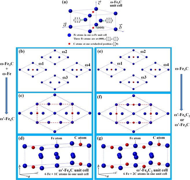
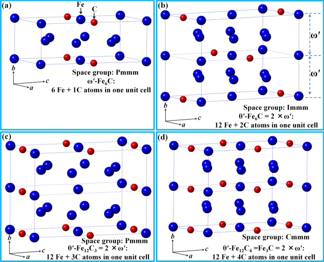
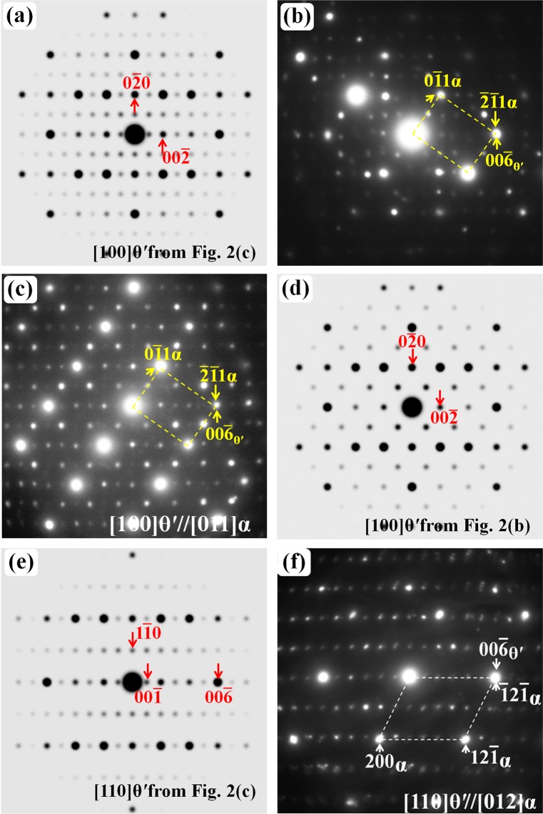
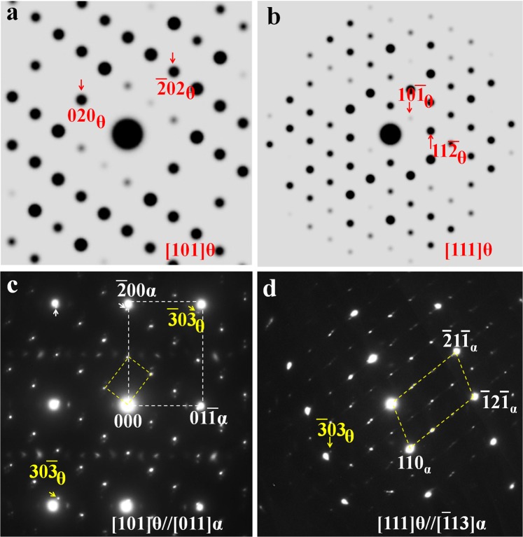
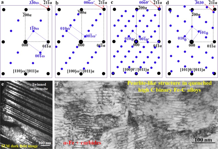
Carbon steel is strong primarily because of carbides with the most well-known one being θ-Fe3C type cementite. However, the formation mechanism of cementite remains unclear. In this study, a new metastable carbide formation mechanism was proposed as ω-Fe3C → ω'-Fe3C → θ'-Fe3C based on the transmission electron microscopy (TEM) observation. Results shown that in quenched high-carbon binary alloys, hexagonal ω-Fe3C fine particles are distributed in the martensite twinning boundary alone, while two metastable carbides (ω' and θ') coexist in the quenched pearlite. These two carbides both possess orthorhombic crystal structure with different lattice parameters (aθ' = aω' = aω = [Formula: see text]aα-Fe = 4.033 Å, bθ' = 2 × bω' = 2 × cω = [Formula: see text]aα-Fe = 4.94 Å, and cθ' = cω' = [Formula: see text]aω = 6.986 Å for aα-Fe = 2.852 Å). The θ' unit cell can be constructed simply by merging two ω' unit cells together along its bω' axis. Thus, the θ' unit cell contains 12 Fe atoms and 4 C atoms, which in turn matches the composition and atomic number of the θ-Fe3C cementite unit cell. The proposed theory in combination with experimental results gives a new insight into the carbide formation mechanism in Fe-C martensite.


Conflict of interest statement

The authors declare no competing interests.

Figures

Figure 1
Figure 1
Atomic structure of various carbides. (a) Unit cell of ω-Fe3C crystal structure. (b) Two ω-Fe3C and two ω-Fe unit cells projected along their c axes. (c) Coarsening of the four unit cells of the ω-Fe3C and ω-Fe in (b) results in the formation of new carbide (ω′-Fe6C) outlined by red dashed lines. (d) The ω′-Fe6C unit cell can have an orthorhombic structure and lattice parameters (aω′ = 4.033 Å, bω′ = 2.47 Å, and cω′ = 6.986 Å for aα-Fe = 2.852 Å), and C atom at (0.5 0 0). (e) Four ω-Fe3C unit cells. (f) Coarsening of the four ω-Fe3C unit cell in (e) results in the formation of a new carbide (ω′-Fe6C2 or ω′-Fe3C) with the same crystal structure and lattice parameters as the ω′-Fe6C. (g) The ω′-Fe6C2 atomic structure in one unit cell.
Figure 2
Figure 2
Atomic structure of various carbides. (a) Unit cell of one ω′-Fe6C variant with one C atom at (0 0 0.5). (b) New θ′ variant (θ′-Fe12C2 or θ′-Fe6C) formed by merging the ω′-Fe6C variant with one C atom at (0.5 0 0) (Fig. 1(d)) and the ω′-Fe6C variant with one C atom at (0 0 0.5) in (a) along b axis. (c) New θ′ (θ′-Fe12C3 or θ′-Fe4C) variant. (d) New θ′ variant of θ′-Fe12C4 or θ′-Fe3C formed by doubling the ω′-Fe6C2 in Fig. 1(f) along b axis. All θ′ have an orthorhombic unit cell with lattice parameters of aθ′ = 4.033 Å, bθ′ = 2 × 2.47 Å = 4.94 Å, and cθ′ = 6.986 Å for aα-Fe = 2.852 Å).
Figure 3
Figure 3
Electron diffraction patterns of the θ′ variants: (a) Simulated [100] zone axis pattern of the θ′-Fe12C3 carbide. (b) Experimental pattern consisting of the diffraction spots from the [011] α-Fe zone axis and [100] θ′-Fe12C3 carbide. (c) Experimental pattern consisting of three sets of diffraction spots: [011] α-Fe zone axis, [100] θ′-Fe12C3 carbide and [100] zone axis of [100] θ′-Fe12C2 carbide. (d) Simulated [100] zone axis pattern of the θ′-Fe12C2 carbide. (e) Simulated [110] zone axis pattern of the θ′-Fe12C3 carbide. (f) Experimental electron diffraction patterns consisting of the spots from the [012] α-Fe zone axis and [110] θ′-Fe12C3 carbide.
Figure 4
Figure 4
Simulated θ-Fe3C electron diffraction patterns: (a) [101]θ and (b) [111]θ. The corresponding experimental patterns observed along the zone axes of (c) [011]α and (d) [113]α.
Figure 5
Figure 5
Schematic electron diffraction patterns between α-Fe and the (a) ω, (b) ω′, (c) θ′, and (d) the θ-Fe3C carbides. All patterns are along the [011]α zone axis.(e) Dark field TEM image revealing the twinned structure, which corresponds to the ω existing region. (f) TEM bright field image showing the pearlite-like structure corresponding to the existing region of the ω′, θ′, and θ fine carbide region.

References

    1. Andrews KW. The structure of cementite and its relation to ferrite. Acta Metall. 1963;11:939–946. doi: 10.1016/0001-6160(63)90063-4. - DOI
    1. Elsukov EP, Dorofeev GA, Ulyanov AL, Vytovtov DA. On the problem of the cementite structure. Phy. Met. Metallogr. 2006;102:76–82. doi: 10.1134/S0031918X06070106. - DOI
    1. Cottrell AH. A theory of cementite. Mater. Sci. Tech. 1993;9:277–280. doi: 10.1179/mst.1993.9.4.277. - DOI
    1. Chiou WC, Jr, Carter EA. Structure and stability of Fe3C-cementite surfaces from first principles. Surf. Sci. 2003;530:87–100. doi: 10.1016/S0039-6028(03)00352-2. - DOI
    1. Wood IG, et al. Thermal expansion and crystal structure of cementite, Fe3C, between 4 and 600 K determined by time-of-flight neutron powder diffraction. J. Appl. Cryst. 2004;37:82–90. doi: 10.1107/S0021889803024695. - DOI