Review
. 2021 Jul;33(28):e2000717.
doi: 10.1002/adma.202000717. Epub 2020 Apr 9.

Recent Progress on Cellulose-Based Ionic Compounds for Biomaterials

Affiliations
Review

Recent Progress on Cellulose-Based Ionic Compounds for Biomaterials

Yang Yang et al. Adv Mater. 2021 Jul.

Abstract

Glycans play important roles in all major kingdoms of organisms, such as archea, bacteria, fungi, plants, and animals. Cellulose, the most abundant polysaccharide on the Earth, plays a predominant role for mechanical stability in plants, and finds a plethora of applications by humans. Beyond traditional use, biomedical application of cellulose becomes feasible with advances of soluble cellulose derivatives with diverse functional moieties along the backbone and modified nanocellulose with versatile functional groups on the surface due to the native features of cellulose as both cellulose chains and supramolecular ordered domains as extractable nanocellulose. With the focus on ionic cellulose-based compounds involving both these groups primarily for biomedical applications, a brief introduction about glycoscience and especially native biologically active glycosaminoglycans with specific biomedical application areas on humans is given, which inspires further development of bioactive compounds from glycans. Then, both polymeric cellulose derivatives and nanocellulose-based compounds synthesized as versatile biomaterials for a large variety of biomedical applications, such as for wound dressings, controlled release, encapsulation of cells and enzymes, and tissue engineering, are separately described, regarding the diverse routes of synthesis and the established and suggested applications for these highly interesting materials.

Keywords: biomaterials; cellulose; ionic; nanocellulose.


Conflict of interest statement

The authors declare no conflict of interest.

Figures

Figure 1
Figure 1
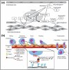
Illustration of the interactions between ionic patterns of GAGs and proteins. HS: heparin sulfate; CS: chondroitin sulfate; DS: dermatan sulfate; KS: keratan sulfate; HA: hyaluronan. Reproduced with permission.[ 37 ] Copyright 2013, Elsevier.
Figure 2
Figure 2
GAG‐binding proteins promote anticoagulation and anti‐inflammation. a) HS binds antithrombin, while DS binds HCII to inhibit thrombin and factor Xa. Reproduced with permission.[ 29 ] Copyright 2010, Elsevier. b) GAGs‐capturing chemokines facilitate leukocyte rolling and extravasation to inflamed tissue. Reproduced with permission.[ 38 ] Copyright 2016, Elsevier.
Figure 3
Figure 3
Characteristic 13C‐NMR spectra (110–55 ppm) of: a) CS with DS of 2.15, b) CS with DS of 0.97, and c) CS with DS of 0.4 in D2O at RT showing the chemical shifts of corresponding carbon atoms for the determination of partial DS ascribed to sulfate groups at a particular position at cellulose backbone. Reproduced with permission.[ 55 ] Copyright 2010, Springer Nature.
Figure 4
Figure 4
13C NMR spectrum of cellulose (3‐carboxypropyl)trimethylammonium chloride ester, degree of substitution 0.75 acquired in DMSO‐d6. Reproduced with permission.[ 99 ] Copyright 2013, American Chemical Society.
Figure 5
Figure 5
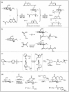
Diverse routes for preparing positively charged cellulose derivatives. a) Scheme for synthesis of cellulose 2‐[(4‐methyl‐2‐oxo‐2H‐chromen‐7‐yl)‐oxy]‐ acetates and cellulose 2‐[(4‐methyl‐2‐oxo‐2H‐chromen‐7‐yl)oxy]‐acetate‐[4‐(N,N,N‐trimethylamonium) chloride] butyrates by in situ activation of 2‐[(4‐methyl‐2‐oxo‐2H‐chromen‐7‐yl)oxy]acetic acid and (3‐carboxypropyl)trimethylammonium chloride with N,N‐carbonyldimidazole (CDI) in N,N‐dimethylacetamide/LiCl (DMA/LiCl). Reproduced with permission.[ 101 ] Copyright 2012, Springer Nature. b) Reaction pathway and structure of dextran N‐[(dimethylamino)methylene]‐β‐alanine ester in one step. Reproduced with permission.[ 102 ] Copyright 2016. Elsevier. c) Reaction scheme for the conversion of cellulose with N‐methyl‐2‐pyrrolidone in the presence of p‐toluenesulphonic acid chloride. Reproduced with permission.[ 103 ] Copyright 2011, Springer Nature. d) Reaction scheme for the synthesis of cellulose phenyl carbonate and subsequent aminolysis applying p‐aminobenzylamine to the corresponding cellulose carbamate. Reproduced with permission.[ 104 ] Copyright 2014, Wiley‐VCH.
Figure 6
Figure 6
a) Comparative binding assay of cellulose sulfates versus heparin for FGF‐2 (white bar) and BMP‐2 (black bar). b) Mitogenic activity of selected cellulose sulfates measured by proliferation of 3T3 fibroblasts in the presence of 10 ng mL−1 FGF‐2 and increasing quantities of cellulose sulfates and heparin. CS‐0.92: circle, dotted line; CS‐1.57: triangles, dash‐dot‐dot line; CS‐1.8: rhombus, dash‐sot line; CS‐1.94: triangle, dashed line; heparin: square, solid line. c) Osteogenic activity of selected cellulose sulfates measured by expression phosphatase (ALP) normalized to protein content of cells in the presence of 200 ng mL−1 BMP‐2 and increasing quantities of cellulose sulfates and heparin. CS‐1.57: triangles; CS‐1.94: rhombus; heparin: square. a–c) Reproduced with permission.[ 123 ] Copyright 2013, American Chemical Society. d) Schematic illustration for cell behaviors on multilayers built with chitosan and anionic polysaccharides. The illustration of multilayer formation at pH 4 or 9 based on electrostatic interaction between chitosan as polycation and heparin (left) or cellulose sulfate (right) as polyanion.[ 124 ] e) Cell proliferation measurements after 1 (gray bars) and 3 (black bars) days of C2C12 cell culture in DMEM with 10% FBS on polyanion (heparin or CS) terminated multilayers prepared at diverse pH conditions. d,e) Reproduced with permission.[ 124 ] Copyright 2013, American Chemical Society.
Figure 7
Figure 7
Preparation of sCMC/CMC/gelatin hydrogels and bioactivities. a) Scheme of enzymatically crosslinked sCMC/CMC/gelatin hydrogels for delivery of cells and TGF‐β1 for cartilage tissue engineering. b) Cumulative percentage release of TGF‐β1 from CMC/gelatin and sCMC/CMC/gelatin hydrogels. c) Histological analysis of cell‐seeded hydrogels cultured for 28 days in vitro with and without TGF‐β1. a–c) Reproduced with permission.[ 121 ] Copyright 2017, Elsevier.
Figure 8
Figure 8
a) Thrombin time (○) and partial thromboplastin time (▪) plotted versus DSS of CS at a sample concentration of 2.5 μg mL−1. b) Thrombin time (left) and partial thromboplastin time (right) of CS with total DSS of 0.95, but different distributions of sulfate groups within AGUs: (●) derivatization predominantly at 2‐O‐position; (▪) derivatization only at 6‐O‐position, and (▴) derivatization to the same extent at 2‐O‐, 3‐O‐, and 6‐O‐position. a,b) Reproduced with permission.[ 142 ] Copyright 2001, Elsevier. c) Schematic illustration for anticoagulant CS‐coated PET surfaces prepared via layer‐by‐layer assembly of polysaccharides (CS: cellulose sulfate; Ch: chitosan; AEA‐C: 6‐deoxy‐6‐(2‐aminoethyl)aminocellulose; BAEA‐C: 6‐deoxy‐6‐(2‐aminoethyl)aminocellulose). d) Free hemoglobin released from nonmodified PET foils and ones coated with polysaccharides. c,d) Reproduced with permission.[ 147 ] Copyright 2011, Wiley‐VCH.
Figure 9
Figure 9
a) Scheme of Ag/Ag@AgCl/ZnO hydrogel to inhibit antibacterial activity. b) Ability of the hydrogels in killing E. coli and S. aureus under simulated sunlight for 20 min. c) In vivo study on the effects of treatment of S. aureus‐induced wound infections by hydrogels and the corresponding wound photographs of rats at days 0, 2, 4, 8, and 14. d) In vivo analysis of blood of the numbers of white blood cells and neutrophils in whole blood extracted from rats after treatment with hydrogels for 2, 4, 8, and 14 days. H1: control hydrogel; H2: Ag/Ag@AgCl hydrogel; H4: the representative Ag/Ag@AgCl/ZnO hydrogel; H6: ZnO hydrogel. a–d) Reproduced with permission.[ 157 ] Copyright 2017, American Chemical Society.
Figure 10
Figure 10
CMC/GO composite hydrogels for loading and release of DOX and the effect of anticancer ability. a) Schematic illustration for the preparation of DOX‐loaded CMC/GO nanocomposites. b) DOX release from the CMC/GO nanocomposite hydrogel at pH 6.8 or pH 7.4 in PBS solutions. c) MTT viability assay of SW480 cells treated with free DOX and CMC/GO+DOX at corresponding concentrations of the complexes between 0 and 32 × 10−3 m. a–c) Reproduced with permission.[ 164 ] Copyright 2017, Elsevier.
Figure 11
Figure 11
CMCC gels loaded with IL‐10 and its effect on the retinal injury. a) IL‐10 releasing measurement in vitro. b) Representative retinal section images of control, I/R + PBS, I/R + Gel or I/R + Gel/IL‐10 group were attained by H&E staining and the corresponding quantitative total retinal thickness and western blotting analysis of apoptotic and antiapoptotic proteins of rRECs. a–c) Reproduced under the terms of the CC‐BY Creative Commons Attribution 4.0 International License (https://creativecommons.org/licenses/by/4.0/).[ 167 ] Copyright 2018, The Authors, published by John Wiley & Sons Ltd and Foundation for Cellular and Molecular Medicine.
Figure 12
Figure 12
Schematic representation for a) the enzyme immobilization on amino cellulose surfaces and b) coupling agents. Reproduced with permission.[ 170 ] Copyright 2019, John Wiley & Sons Ltd.
Figure 13
Figure 13
Schematic composition of a rapid flow‐through immunoassay based on coatings of ω‐amino cellulose carbamate. Reproduced with permission.[ 170 ] Copyright 2019, John Wiley & Sons Ltd.
Figure 14
Figure 14
Schematic composition of a rapid flow‐through immunoassay based on coatings of ω‐aminocellulose carbamate. Reproduced under the terms of the CC BY Attribution 3.0 Unported license.[ 172 ] Copyright 2013, The Authors, published by IntechOpen.
Figure 15
Figure 15
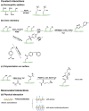
Morphology of three main kinds of nanocellulose: a) TEM image of CNCs. Reproduced with permission.[ 179 ] Copyright 2012, Elsevier. b) TEM image of CNFs. Reproduced with permission.[ 180 ] Copyright 2007, American Chemical Society. c) BC pellicle and SEM image. Reproduced with permission.[ 181 ] Copyright 2016, Elsevier. d) Various ionic nanocellulose prepared by diverse surface modification techniques, including sulfonation, phosphorylation, oxidation, amination and cationic modification.
Figure 16
Figure 16
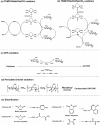
a–d) Sulfonation (a,b,d) and desulfation (c) process of nanocellulose.
Figure 17
Figure 17
Diverse routes to prepare carboxylated nanocellulose. Schematic diagrams for the oxidation of cellulose by: a) TEMPO/NaBr/NaClO in water at pH of 10–11. b) TEMPO/NaClO/NaClO2 in water at neutral or slightly acidic pH values. c) APS oxidation, d) periodate and chlorite oxidation, and e) esterification using organic acids, respectively. a,b) Reproduced with permission.[ 198 ] Copyright 2011, Royal Society of Chemistry. e) Reproduced with permission.[ 210 ] Copyright 2016, American Chemical Society.
Figure 18
Figure 18
Synthetic routes for cationic CNCs via covalent and noncovalent interaction: a) cationic modification of nanocellulose using chemical grafting by nucleophilic ring‐opening of the epoxide moiety, b) click chemistry, c) polymerization on the surface, and d) surface modification of nanocellulose using physical adsorption with cationic molecules or polymers.
Figure 19
Figure 19
Schematic diagram depicting the synthesis of CNC‐graft‐PDMAEMA (CNC‐SS‐PD) via SI‐ATRP and the gene delivery process. Reproduced with permission.[ 235 ] Copyright 2015, American Chemical Society.
Figure 20
Figure 20
A,B) Mixed field and fluorescence‐microscopy images comparing the uptake of CNC‐FITC (upper) with CNC‐RBITC (lower) by Sf9 cells at pH (A) 5 and pH 6.5 (B). Cells were incubated with CNC‐FITC or CNC‐RBITC during 3 h experiment at corresponding pH values, and then fixed for confocal microscope measurement. A,B) Reproduced with permission.[ 231 ] Copyright 2010, American Chemical Society.
Figure 21
Figure 21
A) Preparation routine of single‐membrane and double‐membrane microsphere hydrogels and the images of: a) SA (sodium alginate)/CCNC (cationic CNCs) single‐membrane microsphere hydrogel and b) SA/CCNC‐1 h double‐membrane microsphere hydrogel; B) proposed complexing drug release model for the double‐membrane hydrogel with the formation of cationic CNCs and anionic alginate at pH 7.4. A,B) Reproduced with permission.[ 220 ] Copyright 2016, American Chemical Society.
Figure 22
Figure 22
a) Schematic illustration of on‐demand dissolvable self‐healing hydrogels for deep partial‐thickness burn wound healing. b–d) Wound healing process: b) images of a representative wound site from each group taken on the postinjury days 0, 4, 8, 10, 12, and 14. c) unclosed wound area rate of an initial wound untreated or treated with petrolatum gauze, hydrogel, and hydrogel with glycine on the day 0, 2, 4, 6, 8, 10, 12, and 14. Values are mean ± standard deviation (SD) for each group. ns p > 0.05, *p ≤ 0.01, ***p ≤ 0.001. d) Hemotoxylin and eosin (H&E) staining and Masson's trichrome staining of wounds on day 14. a–d) Reproduced with permission.[ 252 ] Copyright 2018, American Chemical Society.
Figure 23
Figure 23
A) Fabrication process for 3D printing scaffolds using TEMPO CNF/alginate hydrogels. B) Scaffolds printed in diverse forms and designs from the optimum hydrogel formulation. Morphology of wood pulp CNCs and rheological behaviors of aqueous CNC inks of varying solid loading. A,B) Reproduced with permission.[ 257 ] Copyright 2018, American Chemical Society. C) Transmission electron image of the anisotropic CNC particles (scale bar: 500 nm). Inset: Photograph of an aqueous dispersion of wood pulp CNCs (0.1 wt%) placed between cross‐polarizers. D) Steady‐shear and E) oscillatory rheological measurements (frequency = 1 Hz) for the aqueous CNC inks of increasing solid loading (6, 8, 20, and 40 wt% CNCs). F) Shear yield stress of these CNC inks (note: dotted lines in (F) denote the transition from differential to plug flow; inset: 20 wt% aqueous CNC ink in glass vial with 2.5 cm in diameter). C–F) Reproduced with permission.[ 258 ] Copyright 2017, Wiley‐VCH.
Figure 24
Figure 24
Organic antibiotics widely used in nanocellulose‐based antimicrobial materials. Reproduced with permission.[ 274 ] Copyright 2018, Wiley‐VCH.
Figure 25
Figure 25
A,B,D) Shape recovery behavior of a CNF scaffold. A,C) Photographs of CNFs and chitin nanofibril scaffolds with 10 mm edge length. E–H) Bright‐field microscopy after ALP live staining and I–L) fluorescence microscopy after staining the actin filaments with Alexa Fluor 488 Phalloidin (green) and nuclei with DAPI (blue) of: E,I) CNF films, F,J) CNF–Gel–CaPO4 films, G,K) chitin film, and H,L) chitin–Gel–CaPO4 films. M,O) Bright‐field microscopy after ALP live staining of CNF–Gel–CaPO4 and chitin–Gel–CaPO4 scaffolds after sectioning to 1 mm thickness (the insets show the homogeneous ALP live stain in the scaffolds; scale bars 10 mm). N,P) SEM images of a confluent cell layer in a CNF–Gel–CaPO4 scaffold and well‐adherent HSMCs on a less densely populated area of the chitin–Gel–CaPO4 scaffold. A–P) Reproduced with permission.[ 284 ] Copyright 2015, Wiley‐VCH.
Figure 26
Figure 26
Biological characterization of the nanocomposite 3D hydrogels using encapsulated hASCs after 21 days of culture. a) Confocal images of immunolabeled samples against TNC (green), cell nuclei (blue), and cytoskeleton (scale bars = 200 μm). b) Nuclei aspect ratios of cells cultured in isotropic and anisotropic (400 mT) hydrogels reinforced with 1% (w/v) CNCs. Evaluation of cytoskeleton c) and the TNC deposition d) directionality by the encapsulated cells. e) Quantification of tendon‐related marker TNC expression normalized with nuclei area. Statistical significance: ****p < 0.0001. a–e) Reproduced with permission.[ 285 ] Copyright 2019, American Chemical Society.
Figure 27
Figure 27
Chemical structure of fluorescent labeling molecules grafted on CNCs. Reproduced with permission.[ 47 ] Copyright 2014, Elsevier.

References

    1. Moon R. J., Martini A., Nairn J., Simonsen J., Youngblood J., Chem. Soc. Rev. 2011, 40, 3941. - PubMed
    1. a) Zhu H. L., Luo W., Ciesielski P. N., Fang Z. Q., Zhu J. Y., Henriksson G., Himmel M. E., Hu L. B., Chem. Rev. 2016, 116, 9305; - PubMed
    2. b) Gui Z., Zhu H. L., Gillette E., Han X. G., Rubloff G. W., Hu L. B., Lee S. B., ACS Nano 2013, 7, 6037. - PubMed
    1. Fagette P., ASAIO J. 1999, 45, 238. - PubMed
    1. Lavanya D., Kulkarni P., Dixit M., Raavi P. K., Krishna L. N. V., Int. J. Drug Formulation Res. 2011, 2, 2.
    1. Mahiout A., Meinhold H., Kessel M., Schulze H., Baurmeister U., Artif. Organs 1987, 11, 149. - PubMed

LinkOut - more resources