. 2020 Apr 30;20(9):2549.
doi: 10.3390/s20092549.

Hybrid Coils-Based Wireless Power Transfer for Intelligent Sensors

Affiliations

Hybrid Coils-Based Wireless Power Transfer for Intelligent Sensors

Mustafa F Mahmood et al. Sensors (Basel). .

Abstract

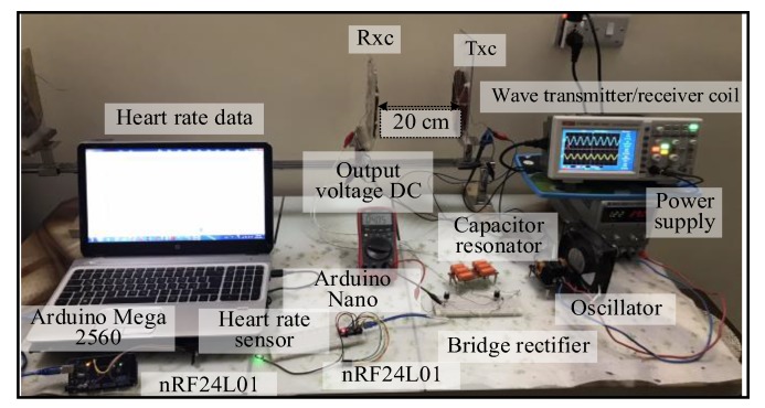
Most wearable intelligent biomedical sensors are battery-powered. The batteries are large and relatively heavy, adding to the volume of wearable sensors, especially when implanted. In addition, the batteries have limited capacity, requiring periodic charging, as well as a limited life, requiring potentially invasive replacement. This paper aims to design and implement a prototype energy harvesting technique based on wireless power transfer/magnetic resonator coupling (WPT/MRC) to overcome the battery power problem by supplying adequate power for a heart rate sensor. We optimized transfer power and efficiency at different distances between transmitter and receiver coils. The proposed MRC consists of three units: power, measurement, and monitoring. The power unit included transmitter and receiver coils. The measurement unit consisted of an Arduino Nano microcontroller, a heart rate sensor, and used the nRF24L01 wireless protocol. The experimental monitoring unit was supported by a laptop to monitor the heart rate measurement in real-time. Three coil topologies: spiral-spiral, spider-spider, and spiral-spider were implemented for testing. These topologies were examined to explore which would be the best for the application by providing the highest transfer power and efficiency. The spiral-spider topology achieved the highest transfer power and efficiency with 10 W at 87%, respectively over a 5 cm air gap between transmitter and receiver coils when a 200 Ω resistive load was considered. Whereas, the spider-spider topology accomplished 7 W and 93% transfer power and efficiency at the same airgap and resistive load. The proposed topologies were superior to previous studies in terms of transfer power, efficiency and distance.

Keywords: arduino; heart rate sensor; nRF24L01; transfer efficiency; transfer power.


Conflict of interest statement

The authors declare no conflict of interest.

Figures

Figure 1
Figure 1
Block diagram of the use of a magnetic resonator coupling (MRC) for a heart rate sensor.
Figure 2
Figure 2
A method of wrapping (a) spiral coil and (b) spider coil.
Figure 3
Figure 3
Types of coils (a) spiral coil and (b) spider coils.
Figure 4
Figure 4
A snapshot of the MRC system at 7 cm for first topology at load.
Figure 5
Figure 5
A snapshot of the MRC system at 9 cm for first topology for real time.
Figure 6
Figure 6
A snapshot of the MRC system at 7 cm for the second topology under load.
Figure 7
Figure 7
A snapshot of the MRC system at 20 cm for the second topology for real time.
Figure 8
Figure 8
A snapshot of the MRC system at 20 cm for the third topology.
Figure 9
Figure 9
The voltage waveforms using the spiral–spiral topology at 7 cm for 50 Ω load: (a) transmitter coil, (b) receiver coil, and (c) voltage load.
Figure 10
Figure 10
The voltage waveforms using the first topology at 9 cm for the measurement unit: (a) transmitter coil, (b) receiver coil, and (c) voltage load.
Figure 11
Figure 11
Performance at different loads for first topology: (a) transfer efficiency at different loads (RL), (b) transfer power at RL, and (c) transfer power on RxC at RL.
Figure 11
Figure 11
Performance at different loads for first topology: (a) transfer efficiency at different loads (RL), (b) transfer power at RL, and (c) transfer power on RxC at RL.
Figure 12
Figure 12
The voltage waveforms using second topology at 7 cm for: (a) transmitter coil and (b) receiver coil.
Figure 13
Figure 13
The voltage waveforms using second topology at 20 cm for measurement unit: (a) transmitter coil, (b) receiver coil, and (c) voltage load.
Figure 14
Figure 14
Performance at different loads for second topology: (a) transfer efficiency at RL, (b) transfer power at RL, and (c) transfer power on RxC at RL.
Figure 14
Figure 14
Performance at different loads for second topology: (a) transfer efficiency at RL, (b) transfer power at RL, and (c) transfer power on RxC at RL.
Figure 15
Figure 15
The voltage waveforms using third topology at 7 cm for: (a) transmitter coil and (b) receiver coil.
Figure 16
Figure 16
The voltage waveforms using the third topology at 20 cm for measurement unit: (a) transmitter coil, (b) receiver coil, and (c) voltage load.
Figure 17
Figure 17
Performance at different loads for third topology: (a) transfer efficiency at RL, (b) transfer power at RL, and (c) transfer efficiency on RxC at RL.
Figure 17
Figure 17
Performance at different loads for third topology: (a) transfer efficiency at RL, (b) transfer power at RL, and (c) transfer efficiency on RxC at RL.
Figure 18
Figure 18
Transfer power at RL based-topologies at: (a) 40 Ω and (b) 200 Ω.
Figure 19
Figure 19
Transfer efficiency of RL based topologies into: (a) 40 Ω and (b) 200 Ω.
Figure 20
Figure 20
Transfer power on RxC at RL based on topologies at (a) 40 Ω and (b) 200 Ω.

References

    1. Curry E.J., Ke K., Chorsi M.T., Wrobel K.S., Miller A.N., Patel A., Kim I., Feng J., Yue L., Wu Q. Biodegradable piezoelectric force sensor. Proc. Natl. Acad. Sci. USA. 2018;115:909–914. doi: 10.1073/pnas.1710874115. - DOI - PMC - PubMed
    1. Wang X., Liu Z., Zhang T. Flexible sensing electronics for wearable/attachable health monitoring. Small. 2017;13:1602790. doi: 10.1002/smll.201602790. - DOI - PubMed
    1. Mahmood M.F., Mohammed S.L., Gharghan S.K. Energy Harvesting-Based Vibration Sensor for Medical Electromyography Device. Int. J. Electr. Electron. Eng. Telecommun. 2020;9 doi: 10.18178/ijeetc.OJS-19209X. - DOI
    1. Moore J., Castellanos S., Xu S., Wood B., Ren H., Tse Z.T.H. Applications of wireless power transfer in medicine: State-of-the-art reviews. Ann. Biomed. Eng. 2019;47:22–38. doi: 10.1007/s10439-018-02142-8. - DOI - PubMed
    1. Shaw T., Mitra D. Metasurface-based radiative near-field wireless power transfer system for implantable medical devices. IET Microw. Antennas Propag. 2019;13:1974–1982. doi: 10.1049/iet-map.2019.0141. - DOI

LinkOut - more resources