. 2020 Jun 4;78(5):926-940.e13.
doi: 10.1016/j.molcel.2020.04.012. Epub 2020 May 4.

Cryo-EM Structure of the Fork Protection Complex Bound to CMG at a Replication Fork

Affiliations

Cryo-EM Structure of the Fork Protection Complex Bound to CMG at a Replication Fork

Domagoj Baretić et al. Mol Cell. .

Abstract

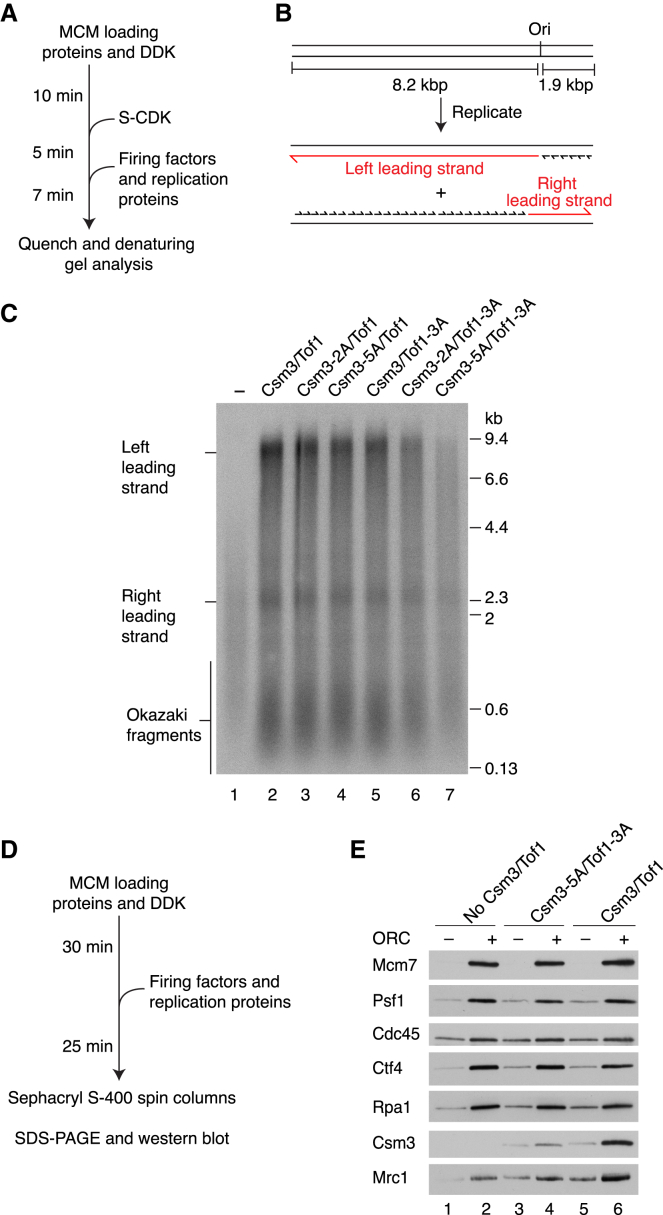
The eukaryotic replisome, organized around the Cdc45-MCM-GINS (CMG) helicase, orchestrates chromosome replication. Multiple factors associate directly with CMG, including Ctf4 and the heterotrimeric fork protection complex (Csm3/Tof1 and Mrc1), which has important roles including aiding normal replication rates and stabilizing stalled forks. How these proteins interface with CMG to execute these functions is poorly understood. Here we present 3 to 3.5 Å resolution electron cryomicroscopy (cryo-EM) structures comprising CMG, Ctf4, and the fork protection complex at a replication fork. The structures provide high-resolution views of CMG-DNA interactions, revealing a mechanism for strand separation, and show Csm3/Tof1 "grip" duplex DNA ahead of CMG via a network of interactions important for efficient replication fork pausing. Although Mrc1 was not resolved in our structures, we determine its topology in the replisome by cross-linking mass spectrometry. Collectively, our work reveals how four highly conserved replisome components collaborate with CMG to facilitate replisome progression and maintain genome stability.

Keywords: CMG helicase; Claspin; Csm3; DNA replication; Fork Protection Complex; Genome Stability; Mrc1; Replisome; Timeless-Tipin; Tof1.


Conflict of interest statement

Declaration of Interests The authors declare no competing interests.

Figures

None
Graphical abstract
Figure 1
Figure 1
Structure of CMG Bound to Csm3/Tof1, Ctf4, and a DNA Fork (A) Silver-stained SDS-PAGE of a representative glycerol gradient fraction of a non-cross-linked sample (fraction 11, Figure S1B) equivalent to fractions used for cryo-EM. (B and C) Cryo-EM density map (B) and corresponding atomic model (C) of a complex assembled as in Figure S1A observed in conformation 1. (D) Model of the Ctf4 trimer bound across the Cdc45-GINS interface of CMG, rendered as a surface. The Ctf4 monomer mediating the interaction with CMG is rendered also as a cartoon.
Figure 2
Figure 2
XL-MS Identifies the Position of Mrc1 in the Eukaryotic Replisome (A) Summary of cross-linking mass spectrometry (XL-MS) for a co-expressed replisome subcomplex (see Table S2 for details of all inter- and intra-subunit cross-links). Lines indicate inter-subunit cross-links. (B) Positions of Mrc1 cross-links detected in XL-MS mapped to the structure of CMG-Csm3-Tof1-Ctf4. The positions of residues observed to cross-link with Mrc1 are indicated by green circles; green labels indicate which Mrc1 residues cross-link to these sites.
Figure 3
Figure 3
Interaction of Eukaryotic CMG Helicase with Fork DNA (A) Cutaway showing the path of DNA approaching and traversing the MCM central channel in conformation 1. (B) Comparison of the MCM C tier between conformations 1 and 2 (subclasses bound to five or three AMP-PNP molecules are shown). (C) Individual MCM ssDNA-binding motif (Mcm2 shown). Three phosphates contacted by the single MCM subunit are colored orange. Ribose and/or base contacts observed in most but not all subunits (see Figures S5A–S5C and S5G). Inset: locations of the ssDNA-binding loops in the MCM primary sequence. (D) Schematic demonstrating the repeating nature of MCM-ssDNA contacts. For variations in sugar/base contacts, see Figure S5G. Bolder colors highlight the ssDNA-binding motif of a single MCM subunit. Phosphates are colored red. (E) MCM N tier loops contacting DNA around the fork junction. Loops are rendered as surfaces, with the Mcm7 NTH separation pin also represented as a cartoon. For (D) and (E), unpaired ssDNA is colored darker pink/orange for the lagging- and leading-strand template, respectively. (F) Detailed view of the strand-separation pin displayed in cryo-EM density (mesh), inserting between the two strands of DNA at the point of unwinding. F363 makes π-π interactions with DNA. ZnF, zinc finger; H2, helix 2; H2I, helix 2 insertion loop; PS1, presensor 1; NTH, N-terminal hairpin.
Figure 4
Figure 4
Csm3/Tof1 Structure (A) Structures of Tof1 and Csm3 shown as cylinders above the MCM N tier (surface representation). Tof1 insertions (cartoon representation): the Ω-loop (orange) and the MCM-plugin (red) are highlighted. The Csm3-binding element (CBE) of Tof1 is colored brown. The positions of the Tof1 head and body are outlined with solid and dashed black lines, respectively. For clarity, dsDNA is not shown. (B) Schematic illustrating the positions of Tof1 helical repeats (numbered 1–9; see Figure S7A for repeat assignment) and Tof1 features (CBE, Ω-loop, and MCM-plugin). The head and body subdivisions are marked with solid and dashed black lines, respectively. (C) Schematic illustration of Csm3 domain architecture with helices α0–α4 labeled. (D) Overview of the Csm3 structure (46–139) and its interface with Tof1 and the Mcm7 ZnF. The Csm3 DNA-binding motif (DBM) is highlighted by a dashed outline. (E) Overview of interactions between Csm3 and the Tof1 CBE. Hydrophobic residues from Tof1 helix α26 are shown.
Figure 5
Figure 5
Tof1 Interactions with MCM and DNA (A) Overview of the Tof1 MCM-plugin (red) and its position on the MCM N tier. Top: the MCM-plugin is shown in cartoon representation above the MCM N tier (surface representation) and structural elements involved in MCM binding are illustrated, as is the location of a DBM. Bottom: schematic illustrating the organization of the MCM-plugin. Structural elements involved in MCM binding are illustrated, together with the specific Mcm subunits that they bind. (B) Overview of Csm3/Tof1 dsDNA contacts at the front of the replisome. The Mcm4, 6, and 7 ZnF domains important for Csm3/Tof1 binding are displayed as cartoons in transparent surfaces. (C) Close-up view of the Csm3/Tof1 dsDNA grip. For simplicity, only the Ω-loop and DBMs are shown. (D) Detailed view of Ω-loop interactions with Mcm6, Mcm4, and dsDNA. Cryo-EM density for the Ω-loop is shown as mesh. (E and F) Detailed views of the Tof1 (E) and Csm3 (F) DBMs with the cryo-EM density shown as mesh.
Figure 6
Figure 6
Csm3/Tof1 DNA Binding Is Important for Replisome Stability (A) Reaction scheme for origin-dependent replication assay. (B) Schematic of the DNA template and anticipated replication products. (C) Origin-dependent replication reaction (7 min) with the indicated Csm3/Tof1 proteins performed as illustrated in (A). Products were separated through a 0.6% alkaline agarose gel. (D) Reaction scheme for protein association experiments. (E) Western blot analysis of a reaction performed as in (D) with the indicated Csm3/Tof1 proteins.
Figure 7
Figure 7
The Csm3/Tof1 dsDNA Grip Is Required for Efficient Fork Pausing (A) Schematic of the template used for replication fork barrier (RFB) experiments and the anticipated products of fork stalling at the RFB. (B) Origin-dependent replication reaction performed for 20 min in the presence of Fob1. The Csm3/Tof1 concentration was increased to 80 nM to increase replication efficiency (Figure S10H). Reaction products were treated with Sma1 prior to denaturing gel electrophoresis to remove heterogeneity in the position of leading-strand initiation (Taylor and Yeeles, 2018). (C) Quantitation of experiments performed as in (B). Error bars represent the SEM from 3 experiments. (D) Spot-dilution assay with Tof1 and Csm3 DBM mutants. 10-fold serial dilutions were plated and grown at 25°C for 3 days.

References

    1. Abid Ali F., Renault L., Gannon J., Gahlon H.L., Kotecha A., Zhou J.C., Rueda D., Costa A. Cryo-EM structures of the eukaryotic replicative helicase bound to a translocation substrate. Nat. Commun. 2016;7:10708. - PMC - PubMed
    1. Abid Ali F., Douglas M.E., Locke J., Pye V.E., Nans A., Diffley J.F.X., Costa A. Cryo-EM structure of a licensed DNA replication origin. Nat. Commun. 2017;8:2241. - PMC - PubMed
    1. Afonine P.V., Poon B.K., Read R.J., Sobolev O.V., Terwilliger T.C., Urzhumtsev A., Adams P.D. Real-space refinement in PHENIX for cryo-EM and crystallography. Acta Crystallogr. D Struct. Biol. 2018;74:531–544. - PMC - PubMed
    1. Alcasabas A.A., Osborn A.J., Bachant J., Hu F., Werler P.J., Bousset K., Furuya K., Diffley J.F., Carr A.M., Elledge S.J. Mrc1 transduces signals of DNA replication stress to activate Rad53. Nat. Cell Biol. 2001;3:958–965. - PubMed
    1. Aria V., Yeeles J.T.P. Mechanism of bidirectional leading-strand synthesis establishment at eukaryotic DNA replication origins. Mol. Cell. 2018;73:199–211.e10. - PMC - PubMed

Publication types

MeSH terms

LinkOut - more resources