

Magnetically driven active topography for long-term biofilm control
- PMID: 32371860
- PMCID: PMC7200660
- DOI: 10.1038/s41467-020-16055-5
Magnetically driven active topography for long-term biofilm control
Abstract
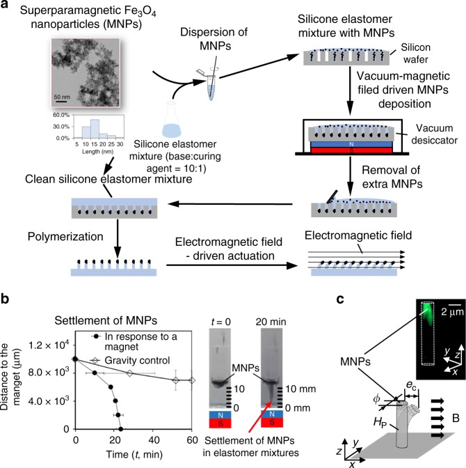
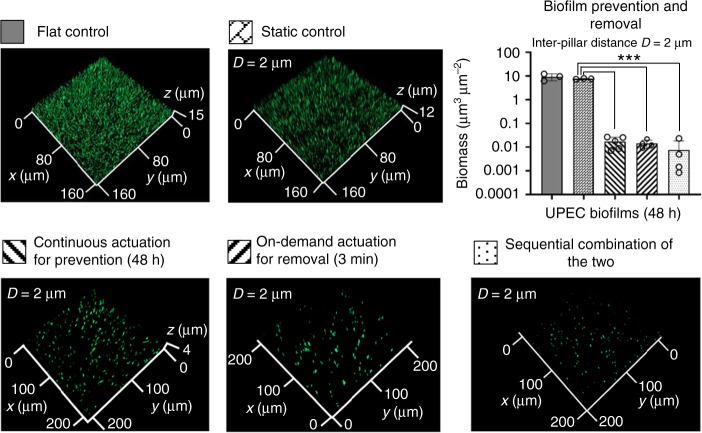
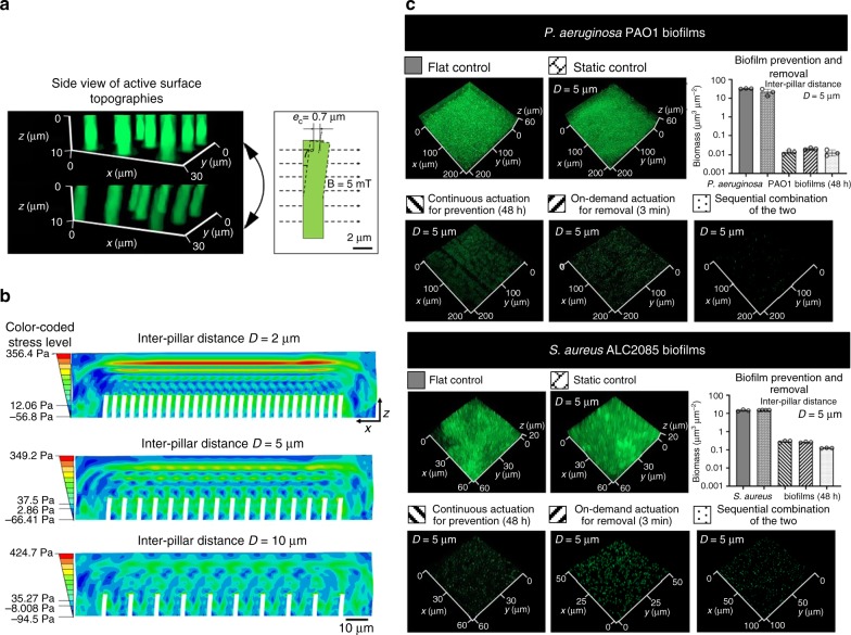
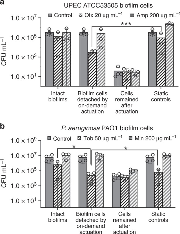
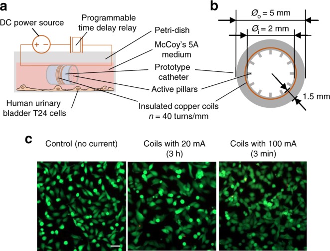
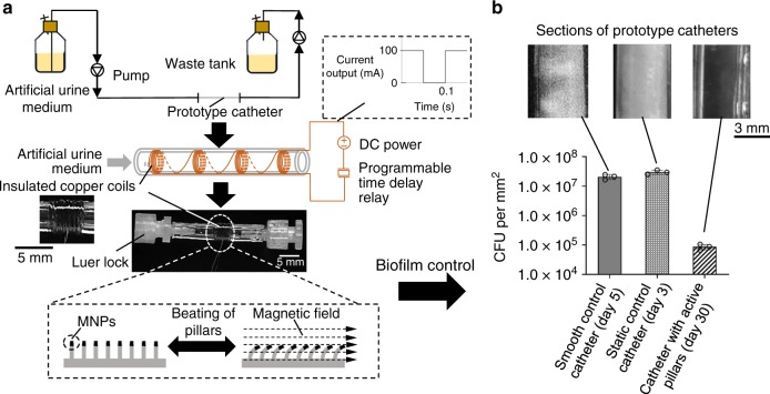
Microbial biofilm formation on indwelling medical devices causes persistent infections that cannot be cured with conventional antibiotics. To address this unmet challenge, we engineer tunable active surface topographies with micron-sized pillars that can beat at a programmable frequency and force level in an electromagnetic field. Compared to the flat and static controls, active topographies with the optimized design prevent biofilm formation and remove established biofilms of uropathogenic Escherichia coli (UPEC), Pseudomonas aeruginosa, and Staphylococcus aureus, with up to 3.7 logs of biomass reduction. In addition, the detached biofilm cells are found sensitized to bactericidal antibiotics to the level comparable to exponential-phase planktonic cells. Based on these findings, a prototype catheter is engineered and found to remain clean for at least 30 days under the flow of artificial urine medium, while the control catheters are blocked by UPEC biofilms within 5 days.
Conflict of interest statement
The authors declare no competing interests.
Figures
Similar articles
-
Inhibition and Inactivation of Uropathogenic Escherichia coli Biofilms on Urinary Catheters by Sodium Selenite.Int J Mol Sci. 2018 Jun 7;19(6):1703. doi: 10.3390/ijms19061703. Int J Mol Sci. 2018. PMID: 29880781 Free PMC article.
-
A novel synthetic synovial fluid model for investigating biofilm formation and antibiotic susceptibility in prosthetic joint infections.Microbiol Spectr. 2025 Jan 7;13(1):e0198024. doi: 10.1128/spectrum.01980-24. Epub 2024 Nov 29. Microbiol Spectr. 2025. PMID: 39612218 Free PMC article.
-
In vitro production of biofilm in a flow cell system in a strain of Pseudomonas aeruginosa and Staphylococcus aureus and determination of efficiency of ciprofloxacin against them.Indian J Pathol Microbiol. 2011 Jul-Sep;54(3):569-71. doi: 10.4103/0377-4929.85095. Indian J Pathol Microbiol. 2011. PMID: 21934223
-
A systematic review and meta-analysis of antibiotic resistance patterns, and the correlation between biofilm formation with virulence factors in uropathogenic E. coli isolated from urinary tract infections.Microb Pathog. 2020 Jul;144:104196. doi: 10.1016/j.micpath.2020.104196. Epub 2020 Apr 10. Microb Pathog. 2020. PMID: 32283258
-
Anti-biofilm peptides as a new weapon in antimicrobial warfare.Curr Opin Microbiol. 2016 Oct;33:35-40. doi: 10.1016/j.mib.2016.05.016. Epub 2016 Jun 16. Curr Opin Microbiol. 2016. PMID: 27318321 Free PMC article. Review.
Cited by
-
Field-Induced Transversely Isotropic Shear Response of Ellipsoidal Magnetoactive Elastomers.Materials (Basel). 2021 Jul 15;14(14):3958. doi: 10.3390/ma14143958. Materials (Basel). 2021. PMID: 34300876 Free PMC article.
-
Role of Staphylococcus aureus's Buoyant Density in the Development of Biofilm Associated Antibiotic Susceptibility.Microorganisms. 2024 Apr 9;12(4):759. doi: 10.3390/microorganisms12040759. Microorganisms. 2024. PMID: 38674703 Free PMC article.
-
Biofilms: Formation, Research Models, Potential Targets, and Methods for Prevention and Treatment.Adv Sci (Weinh). 2022 Oct;9(29):e2203291. doi: 10.1002/advs.202203291. Epub 2022 Aug 28. Adv Sci (Weinh). 2022. PMID: 36031384 Free PMC article. Review.
-
Marine Microbial-Derived Antibiotics and Biosurfactants as Potential New Agents against Catheter-Associated Urinary Tract Infections.Mar Drugs. 2021 Apr 29;19(5):255. doi: 10.3390/md19050255. Mar Drugs. 2021. PMID: 33946845 Free PMC article. Review.
-
Engineering multifunctional surface topography to regulate multiple biological responses.Biomaterials. 2025 Aug;319:123136. doi: 10.1016/j.biomaterials.2025.123136. Epub 2025 Jan 28. Biomaterials. 2025. PMID: 39978049 Review.
References
-
- Centers for Disease Control and Prevention (CDC), CDC at work: preventing healthcare-associated infections. https://cdc.gov/hai/prevent/prevention.html (2010).
-
- Centers for Disease Control and Prevention (CDC), National Healthcare Safety Network (NHSN) Patient Safety Component Manual. Accessed 7 Jan 2017, https://cdc.gov/nhsn/pdfs/validation/2017/pcsmanual_2017.pdf (2018).
-
- Floyd KA, Eberly AR, Hadjifrangiskou M. Adhesion of bacteria to surfaces and biofilm formation on medical devices. Biofilms Implant. Med. Devices. 2017;3:47–95. doi: 10.1016/B978-0-08-100382-4.00003-4. - DOI
Publication types
MeSH terms
Substances
Associated data
Grants and funding
LinkOut - more resources
Full Text Sources
Other Literature Sources
Medical
